Continue to Site

Welcome to our site!

Electro Tech is an online community (with over 170,000 members) who enjoy talking about and building electronic circuits, projects and gadgets. To participate you need to register. Registration is free. Click here to register now.

  • Welcome to our site! Electro Tech is an online community (with over 170,000 members) who enjoy talking about and building electronic circuits, projects and gadgets. To participate you need to register. Registration is free. Click here to register now.

4-20ma current source

Status
Not open for further replies.

therooster

New Member
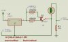
Can someone point me in the right direction to building an adjustable current source.

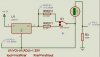
I need 4-20 ma but can use anything that covers that range. Say 0-20ma or even 0-100 ma.

I would also like to be able to use a switch to cover say 0-10 volts. Im thinking I can just switch in a resistor into the circuit to do this.


I know there are specialized chips to this but I would like to use common materials such as voltage regulators or something else inexpensive.
 
rosannadanna :)
It just goes to show ya, if it ain't one thing, it's another

Good point...
 
Last edited:
Hi therooster,

an LM317L (TO92 package) will do the job pretty accurately.

Here is the circuit consisting mainly of the IC and one resistor. The LM317L is wired as a constant current source, and is independent of the input voltage - up the allowed maximum input voltage.

To obtain the standard values of 2 to 10V across the burden resistor (standard 500Ohm) the input voltage should be 3V above the desired output voltage at the burden.

I have drawn the circuit using two fixed value resistors for the lower value of 4mA and the upper of 20mA. The reference voltage, which is decisive for the current is about 1.25V, but might vary from one sample to another.

To make the circuit adjustable from 4 to 20mA I suggest using a fixed value resistor for the upper current value and a 500Ohm pot shunted to the proper value for the lower current value.

Formulas are printed in the screenshots. Maximum current for this IC is 100mA.


Regards

Boncuk
 

Attachments

  • CC01.jpg
    CC01.jpg
    133.1 KB · Views: 7,139
  • CC02.jpg
    CC02.jpg
    129.4 KB · Views: 2,775
This App note shows how you can connect a LM317 Reg as a I source, Only it goes down to 10ma

... which is ten times more than the LM317L. That one goes down to 1mA without problems. Lower currents are impossible and screw up the IC.

Hans
 
You can build a current source with two transistors, that´s the cheapest way I know. For what do You use it?
 
You can build a current source with two transistors, that´s the cheapest way I know. For what do You use it?

... not mentioned the precision resistors it takes to build it with transistors.

An LM371L is 13 Cents! The one resistor might be of any tolerance (variable).
 
It's possible to build a current source with transistors but it varies depending on Vbe which depends on the temperature and the regulation isn't very good.
 
It's possible to build a current source with transistors but it varies depending on Vbe which depends on the temperature and the regulation isn't very good.

That's exactly the reason why I mentioned precision resistors in my post. Precision resistors (metal oxide) have a tolerance of 0.1%, costing 20 Cents each. The other question: are the required values available.

Conclusion: An LM317L + a variable resistor cost far less, the accuracy depends on the LM317L to a great deal and using a 1W wire pot the influence of temperature can be negligated - less wiring too.

Hans
 
Precision resistors don't gain you much because the LM317 has a tolerance of 5%.
 
You could use an opamp...one with common mode input down to 0v like the LM358.

You can google voltage regulator circuits, because they are pretty similar to constant current regulators, only instead of comparing the output voltage to a reference (precision voltage reference) you compare the voltage across a series resistor to the reference.

For low loads, the resistor can be quite high, then its just a question of V=IR. 20ma, through a 100ohm resistor will have 2 volts across it.

I guess it depends on the maximum voltage output for your constant current source, and I assume you want to vary the output via a potentiometer?

google 'low side current sensing' or 'high side current sensing'. I'm sure you'll find some pretty good circuits. Of course others have mentioned many other methods, so I didn't go into detail about using a few transistors. With an opamp and precision voltage reference, you'll have a pretty accurate current source.

Blueteeth
 
Precision resistors don't gain you much because the LM317 has a tolerance of 5%.

In that case it can and must be compensated by the reference resistor. Since it will be variable I don't see any problem.
 
Variable resistors typically have a tolerance of 20% so precision resistors are a waste of money.
 
I believe this is what you are looking for?
 
Many years ago when I did control syatems i built a 4-20 ma tester generator with the 8 point set up, 2-4-6-8-10-12-14-16-18-20. Sorry 9 point system, will find circuit if I can.

Think outside the square then double it
 
Status
Not open for further replies.

Latest threads

New Articles From Microcontroller Tips

Back
Top