Continue to Site

Welcome to our site!

Electro Tech is an online community (with over 170,000 members) who enjoy talking about and building electronic circuits, projects and gadgets. To participate you need to register. Registration is free. Click here to register now.

  • Welcome to our site! Electro Tech is an online community (with over 170,000 members) who enjoy talking about and building electronic circuits, projects and gadgets. To participate you need to register. Registration is free. Click here to register now.

3M Thermofax Bulb Conversion... attempt.

Status
Not open for further replies.

Rave0035

Member
Hi All! Electronics hobbyist here. I've been at the hobby for about 4 years, and have primarily worked with older audio circuits (tube radios, instrument amplifiers, phonographs, etc). I've mostly done troubleshooting and repair - only a few scratch builds under my belt, so I'm still pretty green when it comes to theory and circuit design. I'm hoping you can help me learn!!

A friend of mine recently picked up a 15 amp 3M Thermofax transparency maker for next to nothing, and asked me to give it a once over. It's cleaned up nicely, and I've got it working, but I've found that the bulbs for this particular model are almost impossible to find and change hands for about $275. He wants to use this professionally, so not having replacement bulbs on hand isn't an option... and at that price, he would be better off buying a different 40 year-old Thermofax every time he needed a new bulb.

Long story short, I'd like to convert this unit to use the more common 1350watt bulbs from a 12 amp machine, but don't really know where to start to drop the current sufficiently to keep from exploding bulbs or burning his place down.

I have not been able to get my hands on a circuit diagram for this model yet, but I'm still looking. My questions are:
1) What characteristics of the circuit do I need to know to understand what modifications to make?
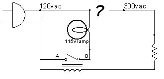
2) Is this truly as simple as wiring some high-wattage resistors in series with the bulb, or am I fooling myself?
3) Does anybody have a schematic for this laying around? :) It's not a complex circuit, but I'd still like diagram to stare at.

Thanks in advance for the help. I really want to learn as I go here!
-Mike, St Paul MN
 
If the two bulbs are the same voltage, and the new bulb needs less current than the old one, you don't need to worry about current.

Consider your wall outlet. You can plug in your 1500 watt (12.5Amp) hair dryer, or your 5 watt (0.05Amp) cell phone charger. Each unit will draw only the current it needs to operate.
 
I agree with ChrisP58. Is there a separate power supply for the lamp circuit or is it powered directly off of mains line voltage?
 
You're both right right. There's a filtered DC supply for the motor, but the amp appears to run on AC.

I have not been able to track down the original bulbs for this machine, but the "easy to find" bulbs are 1350watts (11.25a @ 115VAC). It does appear that the lamp is connect straight through the mains.

Everything on the interwebs about these machines warns that the 12 amp bulbs will not work with a 15 amp machine... perhaps it is just the connections that need to be modified?

I'll get my hands on a 12a bulb and report back. Thanks, guys.

-Mike
 
Everything on the interwebs about these machines warns that the 12 amp bulbs will not work with a 15 amp machine..
Could it be that the 1350 bulb length is shorter than the higher rated bulb?
 
Okie dookie... life got in the way, but I'm back at it. I got my hands on a 12 amp bulb. Here's what I'm finding:
- The "new" bulb is a little longer, and is rated for 115v AC. Here is the datasheet.
- The "old" bulb is rated for 280v AC. I pulled a voltage reading across the lamp, and it looks like it's running just under 300v AC when engaged. Here is the datasheet.

So, here's the rub - how can I convert this to run on line voltage instead of the post-transformer 300vac, but only engage when it's supposed to?

I would kill a man for the wiring diagram of this thing. Any suggestions on where to look for a schematic would be much appreciated.

Thanks in advance for any help!
Mike
 
If I understand you correctly, the original lamp is powered by the secondary winding of a transformer, that currently "engages" as required. The original lamp is rated at 280v a.c. You wish to then swap it for a lamp rated at 120v a.c

I am assuming a couple of things here, but you should check to be certain:

The lamp physically fits the space and lamp holder and has adequate cooling
Nothing else apart from the lamp is being powered directly from the transformer and not through a relay or contactor and the transformer primary winding voltage is 120v a.c

If those conditions are met, you should be able to simply remove the transformer and wire the lamp to the existing wiring currently going to the primary side of the transformer. If some or all of these conditions are not met, you will have to investigate/ modify as appropriate first. For example, a motor, as well as the lamp is powered from the transformer, then simply leave the transformer in and connected to the motor but move the wiring for the lamp to the primary 120v a.c side :)

Some good quality photos may help get some answers if there is any doubt over how it may be wired :)

Incidentally, the links for the lamps that you posted, peg both lamps at 1350W, so the replacement lamp, being that it is rated at 120v a.c as opposed to 280v a.c will be wanting to draw approximately twice the current. So make sure that the wiring to the transformer is capable of handling 12A plus :)
 
Last edited:
So, here's the rub - how can I convert this to run on line voltage instead of the post-transformer 300vac, but only engage when it's supposed to?
I assume that the lamp is either on or off, and that there is no cunning power control for the lamp.

You need to find out if whatever device switches the 280 V lamp on and off is in the 280 V circuit. It could be that the 280 V circuit is switched, or it could be that the 120 V circuit is switched, so that the transformer is turned on and off when the lamp is required.

If the 280 V circuit is switched, or the 280 V from the transformer goes anywhere else other than the lamp, it would be best to keep the transformer. You shouldn't use the 280 V switching device on 120 V because the current will be more than twice as much. I would suggest using a relay. 280 V or 300 V relays will be hard to find, but a 240 V relay with a resistor in series with the coil will be fine. The contacts of the relay would be used to switch the 120 V to the lamp.

If you do use a relay, tell us the specification and we can work out what resistor is needed.
 
Thanks for your replies. I'll try and post photos this evening.

Line voltage comes in to a beefy terminal block that serves as a distribution point to and from the xfmer and all the various circuits. The trouble is, most of the wiring harness is tucked well under the roller assembly, making it all but impossible to see where anything is going without ripping apart all of the mechanical parts of the unit -something I really, really don't want to do.

Tunedwolf - many of your assumptions are correct, but unfortunately the transformer seems to supply a few different circuits. It appears everything other than the motor control (and possibly the vent fan) is AC driven, and the motor control has it's own rectifier circuit.

Diver300 - this seems like a great solution. I have really no experience with relays, but I understand their function in principle. If I understand you correctly, I would wire the relay to the 300v secondary on the transformer, with a resistor in series (value dependent on the voltage rating of the relay used). I would then wire the contacts of the relay to the 120v line voltage and to the bulb. Anytime the 300v hits the relay, it switches the line voltage which turns the lamp on. Am I getting this?

I'll post photos later and be back for more help :) :)

THANK YOU!!! Being able to get this unit functioning will save a good friend hundreds of dollars.
Mike
 
Do you know what technology the bulb is, ie is it filament, gas discharge, fluorescent.
The latter 2 of those both need a ballast inductor, the rating of which is important, if you run a 1200w bulb on a 1500w ballast you'll over run it.
It sounds like its a ac operated filament bulb, can you see the filament through the glass?, its possible but unlikely that the transformer has magnetic shunts in it to limit current.
 
Diver300 - this seems like a great solution. I have really no experience with relays, but I understand their function in principle. If I understand you correctly, I would wire the relay to the 300v secondary on the transformer, with a resistor in series (value dependent on the voltage rating of the relay used). I would then wire the contacts of the relay to the 120v line voltage and to the bulb. Anytime the 300v hits the relay, it switches the line voltage which turns the lamp on. Am I getting this?
You have it basically correct. The relay coil should be wired to where the 280 V lamp is wired. That might be directly across the secondary of the transformer, but there might be a switching device in the way.

The resistor value depends on the coil current as well as its voltage. You might need to do some trial or error with that. The good news is that as long as you have a suitable power rating for the resistor, if its value is too big, the relay just won't operate. If the resistor value is too low, you will get too much voltage on the relay, but a 240 V relay will survive 300 V for a minute or more, so if you have a voltmeter across the relay before you turn on, you can check the voltage in time to turn off, and you can go any buy a larger resistor.
 
It is a filament-style bulb. Thanks for the consideration on that.

Would something like this SPDT work for the relay? The coil voltage is 240vac, and the switching voltage is 277vac max. They're not exactly giving them away, but it sounds like this is what I'd need.

Mike
 
Bump - will that relay fit my needs? Anything else I should be considering?

Also, is this how I would wire this up?

thermofax%252520relay2.jpg


Thanks much!
Mike
 
The relay should be fine. You've got the contact part of the relay correct.

The coil, with its series resistor, should be wired to where the 300 V lamp was connected. In other words, the one side of the relay coil should go to one connection that used to feed the 300 V lamp. One side of the resistor should go to the other connection that used to feed the 300 V lamp, and the other sides of the relay coil and the resistor should be connected to each other and nothing else. (You have shown that)

We don't know, and there is no need to find out, if the 300 V circuit is connected to the 120 V supply. Therefore you should not have any common connections between the contact side of the relay and the coil side of the relay. Your circuit has the contact "A" wired to one side of the coil, which may be wrong. It is safest and easiest to keep the two sides separate.

With that relay, you need a 15 kΩ resistor, rated at 3 W or more. You need to buy a resistor that is rated for 300 V ac. It will have to dissipate between 1 and 2 W. Power resistors run really hot at their full rating, so a larger power rating keeps things cooler. I suggest something like
https://www.digikey.com/product-detail/en/UAL10-15KF8/696-1424-ND/3886628
I know that is very generously rated, and if this were a commercial product it could be worth saving a couple of dollars. However, the full 12.5 W rating for that resistor is with a big heatsink and with a case temperature of around 250 °C, in an ambient temperature of 25 °C. If you don't have heatsink, and it dissipates 2 W, it will still probably be too hot to touch.

That is the cheapest panel-mount 15 kΩ resistor that Digikey offer.

The relay voltage that you will get with 15 kΩ is likely to be between 180 and 250 V, and the power in the resistor between 1 and 2 W. The uncertainty is because the relay data sheet doesn't quote the coil inductance and resistance separately. The inductance and resistance combine to create the impedance. The impedance can be calculated from the fact that the relay takes 10.8 mA at 240 V, but the effect of adding a series resistance is not known exactly without knowing the inductance or resistance. It would be a very good idea to check the voltage across the coil when you have connected up. It should be in the range 180 - 250 V, which should be within the acceptable range for the relay, but if it isn't, tell us the voltage (and measure the 300 V supply under the same conditions) and a more accurate resistor value can be worked out.
 
Thanks, Diver. Awesome write up, and very helpful.

The parts are en route, so I will report back once I have everything wired up and can pull the voltage readings across the relay coil. Stay tuned!
Mike
 
Awesome, I finally get to use those white linen gloves I got at the surplus store!! :woot:
Mike
 
If its a halogen lamp the glass gets so hot it'll turn fingerprint grease to white crud and reduce the brightness and create shadows.

Like the pentode.
 
SUCCESS!!!! Thanks to all for your help (especially Diver300) - this solution works GREAT. The coil of the relay has just over 200v across it when engaged, and the bulb works as designed. Holy cow is it bright/hot when running it without the baffle in place.

The relay and resistor fit really nicely under an existing cowl (shown detached in photos below).

IMG_0555.JPG


IMG_0556.JPG


Thanks again. Awesome forum you guys have here.

Mike
 
Thanks for telling us that it works, and the photos.

Now I've seen how big the relay is, and the fact that you've screwed it and the resistor down, it confirms that the resistor was the right choice, even if it you might have saved a dollar or two on a smaller one.
 
Status
Not open for further replies.

New Articles From Microcontroller Tips

Back
Top