Electro Tech is an online community (with over 170,000 members) who enjoy talking about and building electronic circuits, projects and gadgets. To participate you need to register. Registration is free. Click here to register now.
Welcome to our site! Electro Tech is an online community (with over 170,000 members) who enjoy talking about and building electronic circuits, projects and gadgets. To participate you need to register. Registration is free. Click here to register now.
After converting 30 0 30 volt 5A Ac to DC dual supply with 4 diodes and two 10000 uf capacitors i get out dc 46 0 46 volts . how to regulate this to 30 0 30 volt dc as this supply is to be used for an Amplifier ?
What transformer does the design call for? - using too high a voltage transformer and then trying to regulate the voltage from it makes the overall design a LOT more complicated and unreliable. Did you get the amplifier design from on-line?, if so where?.
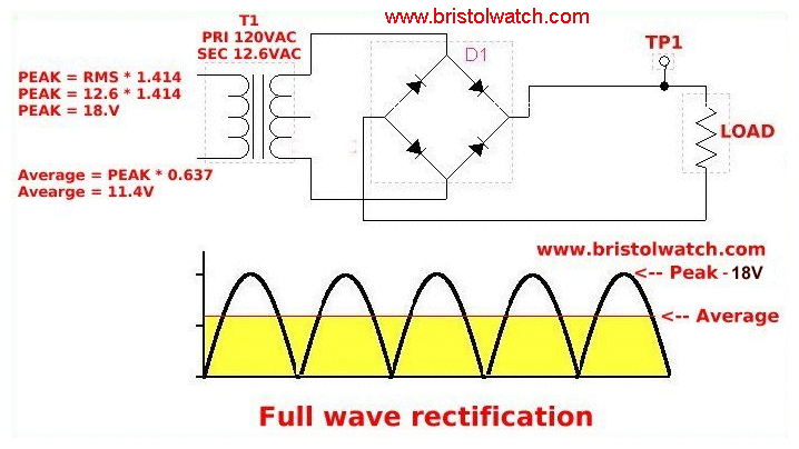
When you rectify AC in such as a power supply, the capacitors charge to the peak voltage of the AC waveform, while the nominal AC voltage is the RMS level; the energy "inside" the waveform curve, if you like.
To put it in a few words: The rectified and smoothed voltage will be around 1.4 times the transformer AC voltage.
The AC voltage will also be a few percent higher than the voltage will be under full load, plus the ripple on the capacitors will increase to some extent as the load increases.
A transformer giving around 21 - 22V out would give close to 30V after rectification.
A regulator to bring the 46V down to 30V for a 5A load woudl be dissipating roughly 75W of heat for each rail, so 150W of heat to get rid of just for the power supply.
A different transformer woudl be a better option..
Certain regular ic's like LM 338 does does regulate + (anode) 30 v 5A but how to handle -(catode) there is one ic LM7918 which Handel's this issue also but gives output of 18 volts only so this can not be used in combination with LM338.as I need to have 30 0 30.
Which means the rectified voltage would be 30 x 1.41 = 42.42V, plus a few percent for transformer regulation (increase off load)
A high quality 300W transformer probably has a regulation factor of roughly 7% or so; eg. the voltage with no load will be something like 7% higher than the voltage at full load.
The output voltage will also depend on how well matched the supply voltage is to the transformer primary fvoltage; eg. a 230V transformer fed from 240V (which is perfectly OK) will be a few percent higher again.
Both positive and negative regulators exist, and low current ones can be boosted with external transistors if needed.
That does not change the fact that each regulator sircuit will be dissipating power (heat) in proportion to the current through it * the voltage drop across it.
So roughly 150W of waste heat (and power used) for each of the positive and negative rails.
The heatsinks would need to be massive!
Which means the rectified voltage would be 30 x 1.41 = 42.42V, plus a few percent for transformer regulation (increase off load)
A high quality 300W transformer probably has a regulation factor of roughly 7% or so; eg. the voltage with no load will be something like 7% higher than the voltage at full load.
The output voltage will also depend on how well matched the supply voltage is to the transformer primary fvoltage; eg. a 230V transformer fed from 240V (which is perfectly OK) will be a few percent higher again.
What transformer does the design call for? - using too high a voltage transformer and then trying to regulate the voltage from it makes the overall design a LOT more complicated and unreliable. Did you get the amplifier design from on-line?, if so where?.
You have to remember that a transformer rated 30VAC at 5A will have a higher voltage when the load is smaller, like 1A. By how much, no one can predict, but you do see it in the rectified DC voltage you get at 46V instead of the expected 42V for a 30VAC/5A transformer. It suggests the transformer AC voltage with no load is around 33V+/- some.
You will never get down to 30V DC with a load, the voltage may drop from 42/46V to something in the high 30's. 30VAC is the average AC voltage, the peaks are much higher and will always provide a higher DC voltage than the AC rated volts. If you load down the transformer heavily, you will exceed the current rating of 5A, and burn up your transformer.
The only solution to get 30VDC with that transformer is to use a voltage regulator on it, somehow.
No! You are not reading the answers or responding to questions!
Each regulator woudl need a heatsink rated at 0.5'C per watt or less, to stop the regulators from melting.
eg. Two something like these may keep the two regulators cool enough so they don't just die.
Find many great new & used options and get the best deals for Fischer Elektronik LA-6-150 High Performance Cooling Heat Sink 0.3°C/W at the best online prices at eBay! Free delivery for many products!
www.ebay.co.uk
A new transformer with the proper ratings would far cheaper. There are several other technical reason that is preferable as well. Not least that at least a third of the available power from the transformer would never get to the actual amplifier, it would just be wasted.
Post a link to the amp & psu designs, so people on here can see what is involved.
This site uses cookies to help personalise content, tailor your experience and to keep you logged in if you register.
By continuing to use this site, you are consenting to our use of cookies.