Continue to Site

Welcome to our site!

Electro Tech is an online community (with over 170,000 members) who enjoy talking about and building electronic circuits, projects and gadgets. To participate you need to register. Registration is free. Click here to register now.

  • Welcome to our site! Electro Tech is an online community (with over 170,000 members) who enjoy talking about and building electronic circuits, projects and gadgets. To participate you need to register. Registration is free. Click here to register now.

3 way PCM

Status
Not open for further replies.

Makaram

Member
Hi all,
I'm designing a product that requires simultaneous recording and streaming of audio.
I'll be using bluetooth to communicate with smartphone. Data in/out of bluetooth module will be I2S.
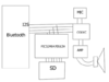
Can I send that I2S to a codec (for mic and speaker) AND a microcontroller (to save to SD) so that I can have the simultaneous recording and playing? If so how?
I've thought of pumping everything through the micro but I want the micro (PIC32MX470f512h) to compress the data before putting on the SD card so it might not be able to cope with everything?

I've attached an image to help with what I mean.
Basically can I tap into I2S without disturbing it
 

Attachments

  • Capture.PNG
    Capture.PNG
    35.8 KB · Views: 183
Last edited:
IIRC The bluetooth audio data interfaces I have seen has been PCM, not I2S. You can use a synchronous serial port on the microcontroller to receive the audio data, or two ports if you wish to record the MIC as well as the SPEAKER audio streams. The uC MOSI pin would connect to the audio data line, and the SCK would go to the bit clock line, if there is one; otherwise the sck would go to a divided version of the PCM/I2S MCLK (or equiv).

The data rate for speech can be quite low (depends on how the BT module is configured, and what quality is acceptable for your application).
 
Yeah I'm struggling to draw the line between PCM and I2S. As far as I can tell I2S is used to transport pcm anyway so that just makes it more confusing.
The WT32 module that I'll be using is capable of both PCM and I2S and the PIC32 has software support for both.

How do I mux the lines together to create 1 audio file? Do I do it in 8bit blocks or can I just OR them together ?
 
PCM and I2S are pretty similar. I2S data or clock is delayed by 1 bit and may or may not have different bit ordering to PCM (this is from memory of looking at some datasheets 5 years ago).

As to "muxing" to create a single audio file with both MIC and SPKR channels, that depends on the audio format. If you are saving as an uncompressed WAV, then the channels are interleaved at the sample level (i.e. channel 1 sample, channel 2 sample, channel 1 sample, etc.).

Unless you meant muxing the hardware lines; it's easier just to use two synchronous serial modules. If you used a single serial module and clocked it at twice the bitrate (with a hardware MUX enabled at the bitrate) you'd get both channels, both the data would be bit-interleaved, and require more processing (you could use a LUT to get the two channel's nibbles out of each databyte quickly).
 
Thanks for your help dude.
So 2 spi ports then combine when saving to SD card is the go you reckon?
I'll have a crack
 
You can use one of the PIC32 timers to divide the MCLK to the bit clock. This can be used to control the Rx Data (MOSI) MUX to select the MIC/SPKR channel.
You will also need to have a clock at twice the bit rate. This will be used to clock in the data from output of the MUX. You can use another timer for this, or the REFCLK divider. This clock feeds the SPI module.
You will need to use the LRCLK (or equiv.) to synchronise/align your SPI reception to the I2S/PCM words.

When you have received 16 bits, you can use a LUT to decode into two bytes (one for each channel), or similarly, from a 32bit word to two 16 bit words. e.g.
Code:
uint32_t muxData = getSPI32();
uint16_t dataChannel1 = (splitLUT[ ((uint8_t*)&muxData)[3] ] << 12)
          | (splitLUT[ ((uint8_t*)&muxData)[2] ] << 8)
          | (splitLUT[ ((uint8_t*)&muxData)[1] ] << 4)
          | splitLUT[ ((uint8_t*)&muxData)[0] ];
muxData >>= 1;
uint16_t dataChannel2 = (splitLUT[ ((uint8_t*)&muxData)[3] ] << 12)
          | (splitLUT[ ((uint8_t*)&muxData)[2] ] << 8)
          | (splitLUT[ ((uint8_t*)&muxData)[1] ] << 4)
          | splitLUT[ ((uint8_t*)&muxData)[0] ];
The splitLUT array/table has 256 entries and contains the values {0..15}, which represent the value of the index if every second bit was removed.
 
Status
Not open for further replies.

Latest threads

Back
Top