Continue to Site

Welcome to our site!

Electro Tech is an online community (with over 170,000 members) who enjoy talking about and building electronic circuits, projects and gadgets. To participate you need to register. Registration is free. Click here to register now.

  • Welcome to our site! Electro Tech is an online community (with over 170,000 members) who enjoy talking about and building electronic circuits, projects and gadgets. To participate you need to register. Registration is free. Click here to register now.

3 watt Luxeon driver circuit

Status
Not open for further replies.

bryan1

Well-Known Member
Hiya Guy's,
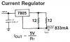
Well my 3 watt lambetian led finally arrived and I'm looking for a decent switchmode circuit to drive the LED. So far I've searched google for ages, searched thru the electrotech forum for past projects with no sucess. I don't want to use the siliconchip version as at $30 each it will be too expensive. Later I'll put up a photo of the box I'm using but it's all Aluminium so that will make an excellent heatsink and I have a 6 volt 4.5 amp hour battery to run the led. One way to do it is use a linear supply via a lm317 but this is wasting about 2.5 watts so thats out the question. But today I will make up a 317 driver circuit just to show you blokes how bright this led is, I powered it last nite using a couple of lithium ion batteries in series and :shock: it does shine a light from the shed to the house.

Any suggestions an a suitable circuit will be apprecieated.

Cheers Bryan :D
 
Well the best thing is a good buck converter, they're very efficient.
The SuperTex HV9910 is a great LED driver. The LED output current is perfectly regulated with a well sized coil, not a PWM.

The HV9910 needs 8v+ to work (upper voltage limit is very high). 6v is too low so I'd say probably a MAX1044 to double the voltage but only use that to supply the Vdd to the HV9910. The current feeding the inductor and the LED would be straight off the battery.
 
Hiya Zach,
The led is rated at 3.6 volts max and 850mA, in the photo below is a pic of the led mounted on the Alumium projector lamp box I scrounged off an old chart recorder. The box is hollow so the electronics will fit inside perfectly. I've also included a simple schematic which is up for scruentary, the purpose of the 2 diodes is to drop the voltage to 3.6 volts and the 1 farad super cap is just an idea, it would be interesting to see what time it takes to discharge the supercap with the idea being all I'll have to do is to charge up the circuit, lockup the shed and have enough time to get down to the house before the led goes out.

Cheers Bryan :D
 

Attachments

  • led_circuit.gif
    led_circuit.gif
    5.4 KB · Views: 7,164
  • led_lamp1.gif
    led_lamp1.gif
    131 KB · Views: 4,210
put te cap betwen the didoes or the cap will discharge in the regulator wich will thurn it in useles heat.
 
I don't have time to look for you, but take a look at mouser. They have a TON of DC-DC converter chips and pre-built units that I'm sure would meet your specifications. It's kind of hard to look without a catalog so I'll do that for ya when I get a chance. Unless you already ahve a catalog.

And c'mon man, take some pics of it powered up!! :lol: :wink:

The silicon-chip one wouldn't work for you, seeing as it is designed for 1W, not 3W.
 
If the diodes conduct with a drop of 1V like most 1N400x rectifiers, the fancy LED won't have enough voltage to be bright.
Doesn't the manufacturer of the LED recommend using a known current to drive it? It's easy to make a regulated current source from a 7805.

The 1F supercap will discharge to about 3V in less than 1 second. Can you run very fast? :lol:
 

Attachments

  • current_regulator.png
    current_regulator.png
    10.3 KB · Views: 9,096
Bryan, your schematic does not include ballast resistance. Some form of current regulation is essential. Diodes are the worst choice. If you have that much voltage gap, either drop the reg and use a resistor or use a current reg. An op amp, transistor, and current-sense resistor can do that.

But really, for this power level, you REALLY should use a current mode buck reg or you're wasting almost half your power. That's tragic for battery life.

The supercap is easy to calculate. Just assume the voltage is constant and the current is proportional to voltage difference divided by the series resistance. Hint- many supercaps have too high an internal resistance to supply hundreds of mA. There are some with low resistance though.
 
Hiya Guy's,
Eh Oznog, thanks for that tip on the supertex HV9910. I looked those chips up and was lucky enough to get a few samples so I can't wait till they get here. In the meantime I'll make up a crude linear supply as I'm not short on the battery side of things as my shed runs on solar and shortly wind generation too :D. The 1 farad supercap I got came out of some old electronic gear I butchered a few years ago so I've no idea of it's specs. As the light will only be used around 5 minutes a night then wasted power won't be a huge problem. Today I'll play around and get the light up and running as the intial trials were awesum.

Cheers Bryan :D
 
Power it correctly using regulated current instead of unregulated voltage and it will be much better than awesome. It might even last for a while. :lol:
 
bryan1 said:
Eh Oznog, thanks for that tip on the supertex HV9910.

It's a great component. There are a couple of things you need to check on:
1. It's mentioned in the spec sheet, but let me point out that a buck converter cannot operate with a constant freq if the buck ratio is under 2:1. And you are. You'll need to go with that "constant on-time mode".
2. Look at where the current feedback resistor is. When the cycle starts, it sets the output high and it charges the gate capacitance abruptly. This may make enough current that it resets the flip-flop prematurely. This is most often a problem when you've chosen a large inductance which otherwise gives a smoother and better regulated output.
Tech support says the key is to add an RC filter into the line between the feedback resistor and the current sense input. It needs to have an RC time constant greater than a magic number of 300nS. Do not go way above this number or it may mess up the regulation.
 
Instead of using a supercap and relying on it's charge to keep the light on long enough, why not just use a wall wart to supply the power with a 555 in monostable mode to keep the light on for however long it takes you to get inside. (with a good sized transistor to handle the current of course 8) )
 
Say, did you also notice the part of the spec sheet where it shows the HV9910 is equally good for HV input, so you can power it right off rectified 120vac?
 
Hiya Guy's,
Well I got the light up and running, I ended up using the 7805 on a heatsink, 1 diode and a 0.47 5 watt sense resistor, oh and the neccerary caps aswell. I ended up with 3.78 volts and 460 mA which is a tad high on the voltage but only 1/2 way on the current. I've really got to get a tripod for my digi camera as taking night shots needs a dead steady hand, but here's a photo taken from behind the light and it really does shine right to the house. Looking up from the house ya nearly blinded if you look into the beam.

Cheers Bryan :D
 

Attachments

  • light_from_shed.gif
    light_from_shed.gif
    58 KB · Views: 2,305
Wow thats one LED shining on the building back there..? 8)
My one watt Luxeon is truely awesome , i see your three Watt is too..
In fact when i was at my brothers place , i compared my 1W'er to his Halogens shining down in his bathroom (wattage unkown )
My battery powered 1 Watt Luxeon was noticeably brighter than his Halogens...
 
bryan1 said:
Hiya Guy's,
Well I got the light up and running, I ended up using the 7805 on a heatsink, 1 diode and a 0.47 5 watt sense resistor, oh and the neccerary caps aswell. I ended up with 3.78 volts and 460 mA which is a tad high on the voltage but only 1/2 way on the current.

I don't understand how you could have made an appropriate power supply with these components. Voltage reg is unimportant; current reg is absolutely critical. It sounds like you have the diode in series with a 0.47 ohm ballast (not current sense) resistor. This is not a great choice. A diode's voltage drop behaviour is opposite the behaviour you need from the ballast. You should use a larger ballast resistance and get rid of the diode if this is what you have.

But didn't you say that you had a 6v battery in the first place? A 7805 cannot work on a 6.0 volt battery. An LDO reg can but not a normal 7805. Even an LDO 5v reg may have trouble depending on your battery. This is a heavy load for some batteries so the battery voltage may drop (especially as the battery gets run down), and since this is generally a "high current" for a 5v reg then the reg's dropout will be higher than the minimum dropout seen at low loads.
 
Hi Oznog,
Bryan changed the battery to 12V when he added the Mickey Mouse voltage-reducing diodes. That's why he needs a heatsink on the 7805.
Yes, now he is using the diode and 0.47 ohm resistor in series with the LED and 5V supply, the numbers add perfectly to cause his low current.
I don't know why he doesn't make the simple current regulator circuit I posted. :(
 
Hiya guy's,
Eh Audioguru, I did make up the current regulator you posted but the voltage stayed around 5 volts and the limited specs I have on the led is 3.6 volt max and 850 mA current. In all the trials I did yesterday the one I made was the most stable and the 7805 doesn't get very hot whereas before it was shutting down all the time cause of the heat. The 0.47 ohm is the lowest resistor I had onhand and I scrounged it off an old printer circuit board.
I'm thinking if I change the 0.47 ohm resistor with a 0.01 ohm 5 watt resistor I should get the current upto where I need, I'll head into town and buy a few low ohm resistors today. Oh and I did change the battery to a 12 volt 7 amp hour but eventually I'll hard wire it into the 12 volt solar array which is 10 nife deep cycle batteries fed off a 80 watt solar panel and soon a 250 watt+ wind genny and the final aim for this project is to make another one based at the house and set them up wireless so I can just use a keyfob transmitter to turn them on and off.

Cheers Bryan :D
 
I couldn't find a 3W LED on Lumileds' Luxeon site.
Their most powerful is the Luxion III which is rated at a 25 degrees C junction temp. Their max is 1.2W without a heatsink.
They don't have a min to max spec for the forward voltage like most other LED spec's have.
They don't show the change in the forward voltage caused by heating.

Their heatsinking document goes on and on and probably shows how to increase the current to get 3W with a proper external heatsink.
Their "How to Drive" document states "LEDs should be driven at a constant current".

In the 7805 current regulator circuit I posted, 5V is developed by the 7805 across the 6 ohms, which results in a constant regulated current output of 833mA. Maybe a Luxion III without a proper external heatsink requires 5V (a coincedence) across it just before it melts. :cry:
 
Status
Not open for further replies.

Latest threads

Back
Top