Continue to Site

Welcome to our site!

Electro Tech is an online community (with over 170,000 members) who enjoy talking about and building electronic circuits, projects and gadgets. To participate you need to register. Registration is free. Click here to register now.

  • Welcome to our site! Electro Tech is an online community (with over 170,000 members) who enjoy talking about and building electronic circuits, projects and gadgets. To participate you need to register. Registration is free. Click here to register now.

3 Laser Switchs - How to activate a LED/Relay?

Status
Not open for further replies.

Fluence

New Member
Hi,

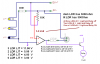
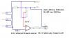
I want to build a 3 Laser Switchs, that when the 3 laser beams are not emitting light, the LED turns on, and when the 3 laser beams are emitting light, the LED turns off.
It's like a laser-alarm.

I've draw this schematic on eagle, but i already tried building it, but it doesn't work, i think i'm messing up in the transistor, that's why i need some advice.

**broken link removed**
 
Your LED has no power source. You want the transistor to look like the attached.

You may also want to read this link and scroll down to the photocell circuits.

You have 3 LDRs in series which isn't likely to work well. Not knowing the LDR resistances (light & dark) it is hard to work from your schematic. Anyway, note the attached transistor circuit to drive the LED or a relay.

Ron
 

Attachments

  • LED.gif
    LED.gif
    4 KB · Views: 328
When the laser is emitting the LDR has 300Ohm.
When it's dark the LDR has 300Kohm.

When the three lasers are intercepted (the LDR will be dark), the relay/LED will light up.

Do you think it's better i come up with another design, or maybe there's a way to build this?
 
Try this, but check your current draws and capabilities.
Kinarfi
 

Attachments

  • untitled.PNG
    untitled.PNG
    23.1 KB · Views: 197
Last edited:
Either one will work, you just have to modify to fit your needs.
Kinarfi
 
Last edited:
If you read the link I suggested earlier you will see among other circuits the attached circuit. Note how the attached circuit looks like the example kinarfi posted. The attached gives two examples, a normally ON and normally OFF LED.

Photocell circuits like these typically use a comparator like the LM339 which is also well described in the link. The attached circuit like most of this type uses a pair of 10KΩ resistors to set a reference on the comparator. These resistors could be replaced with a potentiometer to set a level at which the comparator changes states based on the input from your photocells.

Additionally if you wanted to drive a relay you would add a transistor to the comparator output to handle the relay coil current.

Ron
 

Attachments

  • Photo Cell Circuit.GIF
    Photo Cell Circuit.GIF
    4.7 KB · Views: 214
Thanks Kinarfi, i'll build it when i get to my office.

Ye Ron, i'll use it to drive a relay, this all "project" is like a laser-alarm but with a "fail-safe" system, that instead of one alarm condition (1 laser being interrupted) it uses 3 alarm conditions to give the alarm.

For example, if a bird cross the lasers, the alarm doesn't sound, but if a person crosses the lasers, it will trigger the siren/etc.
 
Last edited:
Trying figure out what you need, but in my first drawing, any one laser beam being broke with activate the LED. all three must be lit to get the 6.3V and with just one broke, the voltage goes to 40 mv, with 2, it goes to 20 mv and all 3 broke gives you 13mv. If you want to light the LED when 2 beams are broken and not just one, you will need the change the series resistor, and the use of potentiometer sounds like a good idea also. I have redrawn my drawing and made some changes based on what has been posted.

Changed the drawing a few times, think it's correct now.
Kinarfi
 

Attachments

  • untitled.PNG
    untitled.PNG
    35.6 KB · Views: 191
Last edited:
Status
Not open for further replies.

Latest threads

Back
Top