Continue to Site

Welcome to our site!

Electro Tech is an online community (with over 170,000 members) who enjoy talking about and building electronic circuits, projects and gadgets. To participate you need to register. Registration is free. Click here to register now.

  • Welcome to our site! Electro Tech is an online community (with over 170,000 members) who enjoy talking about and building electronic circuits, projects and gadgets. To participate you need to register. Registration is free. Click here to register now.

3 digit up down counter

Status
Not open for further replies.

frenchneco

New Member
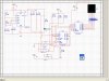
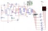
hello guys... i really need some ideas or better yet a complete circuit:D for a 3 digit up down counter...

i've just finished a monostable config 555 for its clock? and its working. then problem starts here. i've tried some circuits in some threads here but none of them are working. simulation or the real thing.

details:
manual switch for up,down,and reset
should use 74LS192
74LS47
7 segment display

i really need help on this guys. the project is due next week.

tnx guys!!!

spread the love... :p
 
hi,
Can you post a circuit of what you have tried to do on this project, other than the 555 timer.
 
hey there! tnx for replying...:)

here's the counter and decoder part... it is only in single digit. after this, the other digits...:D

i don't know where the output of my timer is connected in the 74LS192.
 

Attachments

  • Push button.GIF
    Push button.GIF
    5.6 KB · Views: 2,289
frenchneco said:
hey there! tnx for replying...:)

here's the counter and decoder part... it is only in single digit. after this, the other digits...:D

i don't know where the output of my timer is connected in the 74LS192.

hi,
You are showing manual up/dwn switches into the LS192.
The LS192 has two 'terminal count' outputs, the 'carry output' when the 192 passes thru its maximum up count, this is connected to the next LS192's 'up count' input.

The other output is the 'borrow output' when the LS192 is counting down and it passes thru its 'zero' count, this is connected to 'down count' input of the next LS192.

Connect the 'reset' switch to all the LS192 as you have already done on the 1st stage.

Does this help?
 
frenchneco said:
oh thanks. that would really help.but the problem is, this circuit is not working yet.:D no display.

hi,

This should help with the LS912 interconnections.

Whats the problem with the display?
 
Last edited:
i will try this one out tomorrow at school. for real.:D i'm pretty sure i'll be wasting my time trying to simulate this in multisim....:D

tnx mr. gibbs! i'l post if anything comes up tomorrow.
 
frenchneco said:
here's my multisim circuit. looks like crap.:D by the way, this project is for a basketball scoreboard...:eek:

hi,
That circuit drawing looks fine to me.

Is it possible when you save your drawing, remove the dot grid, otherwise its OK.

Lets know how your project goes.
 
it's not working... there's still no display. we think that the problem is in the decoder part. the output in the 74LS192 is counting as we've seen in the oscilloscope. we can't figure it out.

we tried putting inverters at the output of the decoder(74LS47) and we had a display. 8. it just means all the outputs before the inverters in the decoder are low.

here's the circuit. im using multisim for my simulation.
 

Attachments

  • test.JPG
    test.JPG
    44.4 KB · Views: 1,902
As someone who knows nothing about multisim...
...should there be some connections to Vcc and Gnd for U2 and U3?

JimB
 
frenchneco said:
it's not working... there's still no display. we think that the problem is in the decoder part. the output in the 74LS192 is counting as we've seen in the oscilloscope. we can't figure it out.

we tried putting inverters at the output of the decoder(74LS47) and we had a display. 8. it just means all the outputs before the inverters in the decoder are low.

here's the circuit. im using multisim for my simulation.

hi,
Try this change to the 7447 connections

LT pin#3, o/c or high
BI pin#4, o/c or high
RBI pin#5, 0V

Also as Jim says, make sure you have the supplies connected

Lets know how it goes.
 
Last edited:
JimB said:
As someone who knows nothing about multisim...
...should there be some connections to Vcc and Gnd for U2 and U3?

JimB

VCC and Gnd for ICs in multisim are already virtually connected.. if you know what i mean..:D
 
ericgibbs said:
hi,
Try this change to the 7447 connections

LT pin#3, o/c or high
BI pin#4, o/c or high
RBI pin#5, 0V

Also as Jim says, make sure you have the supplies connected

Lets know how it goes.

alright, i'll try this one out.. tnx..=)
 
ericgibbs said:
hi,
Try this change to the 7447 connections

LT pin#3, o/c or high
BI pin#4, o/c or high
RBI pin#5, 0V

Also as Jim says, make sure you have the supplies connected

Lets know how it goes.

the display just blinked 8. is it correct to put inverters after the 74LS47? and why does the count starts at 8?
 
frenchneco said:
the display just blinked 8. is it correct to put inverters after the 74LS47? and why does the count starts at 8?

hi,
No invertors are required with the 7447, the outputs are active low for driving Common Anode LED's.... you are using CA LED's ????

When you press the up/down switches does the counter count and the LS192 output change?

If the LS192 outputs change, does the LED display change?

Do you have an oscilloscope or a voltmeter??

If Yes, then use them to measure the output voltages of the LS192.

The LT 'lamp test' pin on the LS47 will light ALL 7segs [#8] if the BI and RB etc are connected as shown.
 
yes! we finally figured it out. we were just so stupid to see it. the voltage in the display is just high. the preset voltage drop in the multisim program is 1.66V.

we also got the other digits figured out, which came easy since you helped me. we were just laughing at ourselves after, since it was not hard at all. but the only problem is the starting count is not "000". it would either display "999" or "001". we're thinking of connecting it first in the reset? any suggestions?
 
Roomi said:
Use ICM7217 from Maxim.

download the dts from www.maxim-ic.com and u will get what u wanted.....

as i've posted earlier, we specifically need to do it with the given IC, which is 74LS192. but thanks for the suggestion.

using ICM7217 would not help us, because we don't have money to buy one. i'm from the philippines, and i'm pretty hard up on my finances since i'm only a student.:D same goes for my teammates.
 
Status
Not open for further replies.

Latest threads

New Articles From Microcontroller Tips

Back
Top