Continue to Site

Welcome to our site!

Electro Tech is an online community (with over 170,000 members) who enjoy talking about and building electronic circuits, projects and gadgets. To participate you need to register. Registration is free. Click here to register now.

  • Welcome to our site! Electro Tech is an online community (with over 170,000 members) who enjoy talking about and building electronic circuits, projects and gadgets. To participate you need to register. Registration is free. Click here to register now.

230v Outlet Tester

Status
Not open for further replies.

paternoster2012

New Member
Hello,

I'm curious about putting together a 230v receptacle tester as seen here:
how-to-check-electrical-receptacle-polarity-2.jpg

I have found a few schematics online, but they all seem to be designed for 110v
11495d1178925009-outlet-reading-three-prong-tester-schematic.jpg


My mains electric is 230v single phase

Unfortunately the apartment building I am living in is a nightmare when it comes to the wiring.(lack of enforced building codes) Having this simple device would save me a lot of headaches, but I am unable to find anything remotely similar locally.

I picked up some 220v neon indicator lights that came prewired with 150k resistors.

Can anyone get me a ballpark figure of the resistors I need, and tell me if the schematic above would be correct?
 
You can use the neons with their pre-wired resistors as is. Or you could prolong the neon life by adding 100k or so in series with each 150k/neon. The schematic is fine. Remember, mains voltage can KILL you. All parts of this circuit could be LIVE. Take due precautions. If you have doubts about your ability to construct this safely, don't go ahead.
 
To be fair it would be perfectly fine 'as is', just a bit brighter :D

But as you've already got neons pre-wired with 150K it makes sense to use them.

Bear in mind though, that all it does is indicate the wires are connected the correct way round, it doesn't give any indication of the quality or safety of the connections and wiring.

Incidentally, we're in the process of renovating our old premises next door (converting to a shop unit and apartments), and we've been stripping all the old wiring out - we found:

1) The current 'modern' PVC mains wiring (still in use).

2) Older rubber wiring - not in use (I hope)

3) Even older lead wiring - not in use (I hope again)

4) Lead piping for the original gas lighting - EEEKKK!!.
 
I'm a bit familiar with working with mains. However using neon bulbs is new to me.

I have already put this thing together as is. When it is plugged into a socket which I know to be ungrounded all 3 bulbs light up, though DS2 and DS3 are dimmer than DS1. I assume DS3 is using the ground to complete the circuit to DS2 thus powering both bulbs in a series, hence the dimness. Any suggestions as to how to prevent the neons from firing so they show an open ground like the outlet tester above?

The outlet in question will power a PID kiln control with its own built in GFCI breaker. I am more concerned with making sure the Live and Neutral are wired correctly, as that is very important with the GFCI breaker.

This apartment has several reverse polarity outlets as well as several open grounds. I just wanted a quick device to check and now that I put it together it has become a project unto itself and I am a bit unhappy with the fact it won't show an open ground like the 110v receptacle tester
 
Your location is relevant.

The plug you show is, in the US at least, a 110VAC type (single phase), NOT 230VAC (2 phase) type, for instance:
230VAC Plugs.JPG

What do your outlets look like?
If you use a DVM (or VOM, whatever) to check an outlet (from Ground to left, then to right, then across left and right connectors), what voltage levels do you get?
 
I'm in Southeast Asia.
Receptacle is rated at 16a 250v. Voltage is pretty consistent at 230v. L-N=230 L-G=230 N-G=0
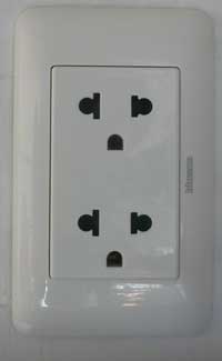
Outlets look similar to this, which is why I am wanting the NEMA 5-15 plug.
electricity-wall-outlet.jpg
 
I'm in Southeast Asia.
Receptacle is rated at 16a 250v. Voltage is pretty consistent at 230v. L-N=230 L-G=230 N-G=0
...
That would be normal for a 15A or 20A branch circuit in the US and Canada, except that here the L-N or L-G would be 120Vac 60Hz. Since here Neutral is tied to Ground in the house distribution panel, there should be zero Volts N-G.

Is Neutral intentionally jumpered to Ground in your system?
 
I'm not quite sure I understand your question.
The mains here is 230v 50hz. There is 0 volts between neutral and ground.

My question here is how to get the neon bulbs to behave like the ones in the 110v tester above. My tester, when connected to an open ground, fires the DS2 and DS3 lamps in a series rather than staying unlit. I'm not familiar with neon bulbs and assume this is related to the resistors.
 
how to get the neon bulbs to behave like the ones in the 110v tester above
The problem is that 230V is enough (>~160V) to strike two neons in series whereas 110V isn't. You would need to make voltage-dividers so that any neon sees only a fraction of the 230V. This would probably require access to the join between the 150k and the neon.
 
The problem is that 230V is enough (>~160V) to strike two neons in series whereas 110V isn't. You would need to make voltage-dividers so that any neon sees only a fraction of the 230V. This would probably require access to the join between the 150k and the neon.

The difference between using a neon lamp at 230V vs 115V is that the current-limiting resistor needs to be increased in resistance (and possibly Wattage).
The data sheet for the various flavors of the ubiquitous NE-2 neon lamp is here.

Since the Lamp drops about 90V when lit, and assuming you are using the 0.6mA variant of the NE2, the current limiting resistor should be increased to (230-90)/0.6m = 220K. The resistor's Wattage rating should be > 220,000*(0.0006) ^2 = 0.079, so 1/4W is ok
 
I dont want to be a killjoy, how about getting a cheap 3 neon tester from ebay 99p, and using a travel adaptor.
I have one on my bench plugged in all the time.
 
I dont want to be a killjoy, how about getting a cheap 3 neon tester from ebay 99p, and using a travel adaptor.
I have one on my bench plugged in all the time.

At issue is operating a 115V tester on 230V. If he bought a 230V tester we wouldn't be having this discussion...
 

How clever!

A regular European outlet combined with American one in a single box. No need for any adapters if you get an American device - if it can take 230V that is, but most chargers will, computers can be easily reconfigured with single switch, perhaps other devices too.
 
SCH-1A.PNG

Here is the Circuit I use, with Explainations for the different Light configurations.

Not sure how good it would work on 230 VAC.

Possibly Increase the 3 Vertical 68 K resistors in the schematic to 100K or 120K.
The two horizontal ones should stay as is.
 
Thank you for all the replies

Let me address a few of them:

The problem is that 230V is enough (>~160V) to strike two neons in series whereas 110V isn't. You would need to make voltage-dividers so that any neon sees only a fraction of the 230V. This would probably require access to the join between the 150k and the neon.

Access to the joint isn't a problem. I popped one of the indicator assemblies apart already, which is how I discovered the 150k resistor. I am wondering what the best way to lower the voltage to the correct level to prevent the neons from firing in a series.


The difference between using a neon lamp at 230V vs 115V is that the current-limiting resistor needs to be increased in resistance (and possibly Wattage).
The data sheet for the various flavors of the ubiquitous NE-2 neon lamp is here.

Since the Lamp drops about 90V when lit, and assuming you are using the 0.6mA variant of the NE2, the current limiting resistor should be increased to (230-90)/0.6m = 220K. The resistor's Wattage rating should be > 220,000*(0.0006) ^2 = 0.079, so 1/4W is ok

I assume this is a question of selecting the right resistor. Your suggestion of 220k has been noted. Would adding a 1/4W 68k resistor in a series to each bulb bring me close enough to 220k to prevent the neon bulbs from firing in a series?

At issue is operating a 115V tester on 230V. If he bought a 230V tester we wouldn't be having this discussion...

Unfortunately I am unable to find any type of outlet tester in this country. Ordering one from overseas and paying $40 shipping plus customs fees kind of contradicts the low cost aspect of the outlet tester.

How clever!

A regular European outlet combined with American one in a single box. No need for any adapters if you get an American device - if it can take 230V that is, but most chargers will, computers can be easily reconfigured with single switch, perhaps other devices too.

Anything with its own wallwart or power supply unit seems to do fine. My old alarm clock from university lasted just long enough for me to set the time before it went to the big trash heap in the sky. Lesson learned, and since then I check the input on any device I plug in over here. Saw a friend plug in an expensive 110v turntable... he almost cried.


For the record, I am an American transplant. I'm used to working with 110v, so this 230v combined with neon bulbs (which I am unfamiliar with) has me perplexed. I think it just needs the appropriate resistance to function how I desire.

220k resistance for each bulb has been suggested so I will give that a go and report back, unless anyone has some other recommendation.
 
220k resistance for each bulb has been suggested so I will give that a go and report back, unless anyone has some other recommendation.

Pay attention to post #14 - using just a series resistor isn't going to work, you must have a potential divider as in #14 (otherwise you will get the two neons at once scenario still).
 
A Neon bulb STRIKES with about 90V peak but continues to glow with about only 65V. The difference in voltage allows a simple DC neon flasher to be made with one resistor plus one capacitor.
 
Re posts #14 and #16, you could use all 150k instead of the 68k shown (68k is too low for 230V). That way you can make use of the 150k resistors you already have.
 
Alright, I think I have come up with something....how does it look?
Tester2.png

The thought being properly wired, L1 and L3 would be lit.
If polarity was reversed, L1 and L2 would be lit.
If there were an open ground, L1 should be lit, but would this schematic prevent L2 and L3 from firing?

Here is my math for L2 in event of an open ground
(R2 / (R1 + R2)) * V1 = V2
(150k / (300k + 150k)) * 230v = 76v
If neon strikes at 90v, then 76v should keep the bulb unlit, correct?

Would L3 be lit in this situation? At first glance it seems that it would be faintly lit due to being in a series with the L2 bulb.


Sorry for all the questions. This thing has become a bit of a riddle for me to fuss with. Not used to doing these types of calculations:D
 
Last edited:
Keep the horizontal ones 68K - assuming the previous example worked OK on 110V? (and I presume it did?) then all you're doing is duplicating it with slightly higher resistors (but the same ratio).
 
Status
Not open for further replies.

Latest threads

New Articles From Microcontroller Tips

Back
Top