Continue to Site

Welcome to our site!

Electro Tech is an online community (with over 170,000 members) who enjoy talking about and building electronic circuits, projects and gadgets. To participate you need to register. Registration is free. Click here to register now.

  • Welcome to our site! Electro Tech is an online community (with over 170,000 members) who enjoy talking about and building electronic circuits, projects and gadgets. To participate you need to register. Registration is free. Click here to register now.

22 Watt Amplifier

Status
Not open for further replies.

T-bro

New Member
first of all thanks to everyone who helped me with my last project it worked :D

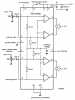
Now, I'm building a 22W amplifier.. to be particular this amplifier: 22 Watt Audio Amplifier

The amplifier is not that big of a problem, I have all the parts i need and i will be just simply screwing the chip to a metal box(yes the box in which the circuit will be in, not a good idea?) and then to be safe I'll put an extra fan on the top of the box to make the chip cool.

Now, I want to build a power supply. Now I'm from Europe so I need to convert 220 AC to 12V DC. This is a problem.. I think I found a right transformer for the job.. a 25VA 220/12V Toroidal transformer. This is the only one that i found that would support the power of the amplifier. I would build the power supply according to this schematic: https://www.circuitstoday.com/wp-content/uploads/2009/05/simple-ups-circuit.jpg
Is that good?

Thanks a lot guys
 
I don't think the 7805 will be big enough to provide 60 watts. Tell us a little about your transformer before we go on.
 
I think the 25VA transformer is a bit marginal for this amplifier if you want to run it at full power, but it will work OK for reasonable output levels.

I would not use the power supply circuit you suggest, it gives a regulated 5V output that you don't need, and the 12V output is unregulated.

I would use the transformer, bridge rectifier and 2200u reservoir capacitor (make sure this is big enough to handle the ripple current) and then an adjustable regulator such as the LM338. This can be easily set for 14V4 output voltage which is the correctl supply voltage for the TDA1554.

I would put a 1u capacitor on the output of the LM338, just to avoid any potential oscillation problems, and possibly a protection diode from output to input as shown in fig. 3 of the LM338 data sheet.

See LM338 data sheet at http://www.datasheetcatalog.org/datasheet/nationalsemiconductor/DS009060.PDF

Hope this helps.
 
OK.. then I'll buy a 35VA 220/12+12V transformer, no big deal it's the same price :D btw any tips on how to mount a toroidal transformer?

Is the LM338 necessary? Because it costs 10 bucks here in Europe. Are there any replacements? Or can I just put a bridge rectifier and then a capacitor in parallel with the output? That is how I learned in school :D
 
The TDA1554 IC produces 22 Whats per bridged output into 4 ohm speakers when its supply is 14.4V. Its produces Whats because the volume control is turned up too high and its output is square-waves with horrible clipping distortion. The added distortion makes the power number higher.
It produces about 14 Watts per channel just before clipping occurs. Its output is about 8 watts per bridged channel into 8 ohm speakers.
It does not need a voltage regulator if the main filter capacitor is large enough.
 
I'll simply be using some small mp3 speakers at first.

What capacity do you think is large enough?
 
Small MP3 speakers are probably 8 ohms, not 4 ohms. The resulting total power of 16W might blow them up.
For a total of 16W the current from a 15V supply is about 1.8A max so use a 5600uF filter capacitor.
 
Ya I thought so :D I'll put a potentiometer(10k) on both outputs not to blow the speakers.

15V supply? The schematic shows a 12V supply and I already found a 12V transformer.
 
Last edited:
A volume control is used at the input of an amplifier, never at the output.

A 12VAC transformer has a peak voltage of 17V which is reduced to 15VDC by the full-wave bridge rectifier. The schematic you found is wrong.
 
I meant the amplifier schematic.. it says that the circuit runs on 12V, not 15V 22 Watt Audio Amplifier

Are you saying that it can work on 15V as well?

Lets sum up. So for the power supply I will need: a 12V DC transformer, a bridge rectifier(does it mater which one?) and a high capacity capacitor to go in parallel with the output?

Thanks for all ur help :)
 
I meant the amplifier schematic.. it says that the circuit runs on 12V, not 15V 22 Watt Audio Amplifier
Are you saying that it can work on 15V as well?
The site you found has schematics with many errors. Simply look at the datasheet for the TDA1554 amplifier IC instead. Its max supply is 18V and all its spec's are with a supply of 14.4V like in a car with the alternator charging the battery.

Lets sum up. So for the power supply I will need: a 12V DC transformer, a bridge rectifier(does it mater which one?) and a high capacity capacitor to go in parallel with the output?
No.
A transformer is AC, not DC. When you rectify and filter it then you get DC. The bridge rectifier must be able to pass 1.8A so use one rated for 5A.
Use a 25V capacitor.
 
Oh ya sorry I wrote it wrong.

Alright.. So i build the circuit according to the schematic, screw the chip to the metal box in which the circuit will be in(I'll put a small fan on top just be sure it stays cool) and put a 10k potentiometer on the input of the amp to control the volume.

As for the power supply.. I'll get a 220V/12V AC toroidal transformer, a 5A bridge rectifier and a 4700uF/25V capacitor in parallel whit the output(small mp3 speakers).

That's the plan correct me if i wrote anything wrong :D
 
To mount the toroidal transformer, just stick a bolt (plus insulated washers) through the hole in the middle.

Andrew
 
just one more question. the volume control potentiometer. how do i wire it up? because when i built a small mp3 amp i wired one end of the double potentiometer on ground, one to left and right out and than the center lead to left and right in. can i do it like that? and how big should the potentiometer be, 10k?
 
The datasheet for the TDA1554 anplifier IC shows that its typical input resistance is 60k ohms and it must use an input coupling capacitor. The capacitor can be about 220nF which is a metalized plastic film type. The volume control can be 10k to 50k ohms per channel and should have an audio taper (logarithmic).

I couldn't find a photo of a volume control for me to mark the input terminal at one end, the ground terminal at the other end and the slider which is the center terminal.
The slider connects to the input coupling capcitor at the input of the amplifier.
 
AG, what is that amp IC you always recommend? I can't remember the PN#
 
An LM3886 is an excellent 50W into 8 ohms or 68W into 4 ohms amplifier when its supply voltage is as high as shown on its datasheet. Its minimum supply is 20V and plus and minus 10V is recommended. Its output power with a 20V supply is low.
 
The datasheet for the TDA1554 anplifier IC shows that its typical input resistance is 60k ohms and it must use an input coupling capacitor. The capacitor can be about 220nF which is a metalized plastic film type. The volume control can be 10k to 50k ohms per channel and should have an audio taper (logarithmic).

I couldn't find a photo of a volume control for me to mark the input terminal at one end, the ground terminal at the other end and the slider which is the center terminal.
The slider connects to the input coupling capcitor at the input of the amplifier.

u haven't really answered my question.. how do i wire the potentiometer? so the slider goes to the input after the capacitor? one wire goes to ground? what about the last wire?
 
u haven't really answered my question.. how do i wire the potentiometer? so the slider goes to the input after the capacitor? one wire goes to ground? what about the last wire?
No.
I said, "The input terminal at one end and the ground terminal at the other end. The slider which is the center terminal connects to the input coupling capacitor at the input of the amplifier."
My sketch shows a TDA1554 amp with two 10k volume controls.
 

Attachments

  • TDA1554 amp.PNG
    TDA1554 amp.PNG
    28.9 KB · Views: 484
  • volume control pic.JPG
    volume control pic.JPG
    5.2 KB · Views: 310
Status
Not open for further replies.

New Articles From Microcontroller Tips

Back
Top