Continue to Site

Welcome to our site!

Electro Tech is an online community (with over 170,000 members) who enjoy talking about and building electronic circuits, projects and gadgets. To participate you need to register. Registration is free. Click here to register now.

  • Welcome to our site! Electro Tech is an online community (with over 170,000 members) who enjoy talking about and building electronic circuits, projects and gadgets. To participate you need to register. Registration is free. Click here to register now.

20watt Bike light

Status
Not open for further replies.

smokengunz

New Member
Hi all I'm new at this so I need some instruction.

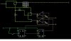
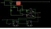
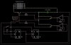
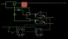
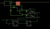
I am trying to build a 20watt Bike light LED driver, multi level dimmer, single push button unit.

I have attached a rough cct diagram. Can I use a 4 bit binary counter (with amplified O/P's) to drive the power transistors?
I have tried to build this already but its a no go

Some Part #

4 bit binary counter: SN74LS93N
Amps: UA741CP
Transistors: BD679
 

Attachments

  • CCT-1.JPG
    CCT-1.JPG
    37.6 KB · Views: 170
More info

Errr i only show half the 4 bit counter in the diagram and the amps are driven by the battery. Im not sure about the feedback loop on the amps either

When i built it the binary counter would output 0.1v on A,B constantly?
 
the idea is that it has 3 different light level settings and off by using the binary counter to control the various trannies.
 
Why is your schematic a negative picture?

Your opamps have no voltage gain so their output is only about +3.5V.
But your LED array probably needs 12V.

Even if you removed the 1k feedback resistors at each opamp so they have voltage gain, their max output will be about 12V and the two transistor emitter-followers will have an output of about 10.5V.

What limits the current in the LED array?
 
i only need the opamps to saturate the base on the two transistors, can they amplify the output from the bit counter enough to do this? why have I got .1 volt comming from the bit counter at logic a and b all the time?

The negative look of the diagram is from a app on the net (circuit simulator) it is a easy tool for drawing with from where I work :)
 
was hoping to control the current in the LED loop by varying the transistor base voltage
The circuit does not change the transistor base voltage.
If you make a different circuit that controls the transistors base voltage then the LEDs will be turned off or they will burn out. The base voltage simply makes the transistor provide enough voltage, with no control for the current.

i only need the opamps to saturate the base on the two transistors
The opamps are followers without any voltage gain. Their output will be only 3.5V (the output of the TTL logic).
The transistors are also followers with a voltage loss of about 1.5V. So the LED array gets only 2.0V and it will not light up.
 
What would you recommend i do to control the current in this loop.
Will changing the resistance in the line feeding the tranny base vary the amount of current going thru the E-C of the transistor?
 
I can get the array to dim using this method in a simple cct.
I need help with the setup of the binary counter and amplifying its output to run the other transistors.
:)
 
More info

the simulation is rough but this shows the idea of the bit counter in action.
 

Attachments

  • CCT-2.JPG
    CCT-2.JPG
    48.4 KB · Views: 131
  • CCT-3.JPG
    CCT-3.JPG
    50.4 KB · Views: 130
  • CCT-4.JPG
    CCT-4.JPG
    38.3 KB · Views: 136
  • CCT-5.JPG
    CCT-5.JPG
    39.7 KB · Views: 134
I am glad to see that you added voltage gain to the opamps.

The simulation is very misleading:
1) Transistors have a wide range of current gain and it is not marked on them (although many years ago the BC549 was labelled A for low gain, B for medium gain and C for high gain). You cannot buy a certain current gain, you get whatever gain they have.
2) The current gain of a transistor changes with its temperature and with the voltage across it.

Simply use the transistors as on-off switches to provide pulse-width-modulation or to switch a different number of current-limiting resistors in series with the LED array.
 
Status
Not open for further replies.

Latest threads

New Articles From Microcontroller Tips

Back
Top