DigiTan
New Member
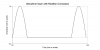
I'm setting up an oscillator with one of those feedback transformers used in CCFLs. So far it's been successful in generating outputs as high as 1,300kV. The problem is the circuit draws an enormous amount of current, even when there's nothing on the high voltage secondary. The energy winds up mostly in the transformer where it heats up above the boiling point.
Everything seems in line with their decription, so I don't think this is a natural drawback of the circuit. It's just eating too much power for some reason. With the exception using L1 = 1mH and C1 = 330nF, mine is exactly the same as in the drawing.
Anyone have an idea of how to improve the efficiency of these Royer-type circuits?
Side question: Can the feedback coil be used to drive a second (identical) oscillator?