Continue to Site

Welcome to our site!

Electro Tech is an online community (with over 170,000 members) who enjoy talking about and building electronic circuits, projects and gadgets. To participate you need to register. Registration is free. Click here to register now.

  • Welcome to our site! Electro Tech is an online community (with over 170,000 members) who enjoy talking about and building electronic circuits, projects and gadgets. To participate you need to register. Registration is free. Click here to register now.

2 transistor circuit help

Status
Not open for further replies.

viri

New Member
# Circuit Wizard - Untitled.jpg
i would like to know whats wrong with my circuit
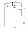
because the motor spin very slow
if i connect the dc source (9 V , 0.5 A ) directly to motor it spin 10 time faster
and is the value of resistor right ???
i calculate it according to this Ic = hFE × IB

many thanks
sorry for my english
 
When using a transistor as a switch assume it has a gain of only 10. So if your motor draws, say, 400mA max then the base current of Q1 will be assumed as 40mA to ensure the transistor saturates, requiring R1 to be ~ 220Ω.
 
With your circuit, Q2 is running as an inverted transistor (collector and emitter functions are swapped). The current gain will be VERY low, possibly less than 1.
You don't need two transistors. See the attachment.
The diode will protect your transistor from the high flyback voltage across the motor which will occur if you omit the diode.
 

Attachments

  • motor driver2.png
    motor driver2.png
    18.6 KB · Views: 170
Status
Not open for further replies.

New Articles From Microcontroller Tips

Back
Top