Continue to Site

Welcome to our site!

Electro Tech is an online community (with over 170,000 members) who enjoy talking about and building electronic circuits, projects and gadgets. To participate you need to register. Registration is free. Click here to register now.

  • Welcome to our site! Electro Tech is an online community (with over 170,000 members) who enjoy talking about and building electronic circuits, projects and gadgets. To participate you need to register. Registration is free. Click here to register now.

2 motor Bi-directional PWM control help

Status
Not open for further replies.

ashrau

New Member
Hi.

I'm trying to make a 2 wheel self-balancing robot - right in the initial phases.

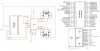
I am using a PIC microcontroller (PIC18F4220 or PIC18F4620) and a L298N Full H-bridge.

I have learned how to use PWM to control speed of the individual motors - but only in one direction.

Currently, I can controle 1 motor for speed and direction using the 2 PWM pins on the PIC. I would like to control both motors for speed and direction (independantly) using the PWM outputs from the PIC. How can I do this with just 2 PWM pins available on the PIC? Do I need a different PIC with more PWM outputs or is there a way to accomplish this using just 2 PWM outputs?

Any help will be highly appreciated!

Thanks.

ashrau
 

Attachments

  • PWMschematic.jpg
    PWMschematic.jpg
    200.4 KB · Views: 1,080
Last edited:
Its not a big issue to control motor ..... check the datasheet of L298 ..... for driving one motor you are giving two pins from PIC to L298 ..... if u give 1 0 to these pins then motor will move in one direction and if you give 0 1 it will move in opposite direction ..... if u still have any problem then u may ask ..... but i would suggest to use transistors for motor drive as L298 current rating is not much but if u use FETs u can drive any motor having any load ....
 
Thanks for the reply! My current circuit diagram is attached.

Here is the issue that I am having with controlling two motors:

I want to control the motor speeds using the PWM function from the PIC. I am using 2 output pins from the PIC to enable/disable the 2 bridges in the L298N. I am doing this by toggling the output b/w HI and LO.

The PIC has only 2 PWM outputs available.

How do I control - through this single PIC - both motors for speed as well as direction? Right now both my PWM outputs from the PIC are tied up with one motor. Do I need a PIC that has more PWM outputs? Or is there a way for me to control both motors through just 2 PWM signals?

The motors that I am using have a peak current (when stalled) of 1.3 A - so the L298N should be O.K to handle the load. I would like to stick to PIC microcontrollers and H-bridges as I am familiar with them.

Thanks again!

Best,
Usman

P.S Some other questions - some explanations on these would be helpful for me as wel:

- Do i need all 4 diodes on each motor? What would be the difference if I used just 2?
- Do I need a seperate capacitor for pin 9 of the L298N?
- Do I need a seperate capacitor for the motors or the current arrangement will be O.K?
 

Attachments

  • PWMschematic.jpg
    PWMschematic.jpg
    200.4 KB · Views: 3,054
sorry for late replying as I ws bzy ..... First thing u can create PWM signal by urself .... PWM is nothing just a signal with limited 1 .... u can create it with any pin not a big issue and L298 is not so gud I have used it with 12V motor n it gets hot .... if u r using heavy motor then i will suggest u to use transistors or relays .....
 
The PIC has only 2 PWM outputs available.

How do I control - through this single PIC - both motors for speed as well as direction? Right now both my PWM outputs from the PIC are tied up with one motor. Do I need a PIC that has more PWM outputs? Or is there a way for me to control both motors through just 2 PWM signals?

You need some logic in front of the in pin that will send the pwm to the correct side of the bridge. It can be gated with a forward reverse signal from the pic.

- Do i need all 4 diodes on each motor? What would be the difference if I used just 2?
Yes
- Do I need a seperate capacitor for pin 9 of the L298N?

I would add a large cap on pin 9--say 100ufd.
- Do I need a seperate capacitor for the motors or the current arrangement will be O.K?

The schematic shows pin 9 and the motor on the same voltage if they are different I would add the 100 ufd, to the motor supply. If that is the case I would then add just a .1 ufd to pin 9.
 
The PIC has only 2 PWM outputs available.

The only pins on the L298 which need a PWM signal are the 2 Enable pins (EnA & EnB) :)

You don't need any logic.

Then simply supply In1 and In2 with a '10' for forward and a '01' for reverse (or vice-versa).
 
Status
Not open for further replies.

New Articles From Microcontroller Tips

Back
Top