my supply is 6V sir, what do you mean for the supply of my counter? its ok to replace 0.01uF to 0.1uF?
hi besoy,
The 6V battery will be OK, dont forget to have the series diode in the battery positive lead to the counter PCB, look at my earlier posts.
The 0.1uF will be OK to use.
")
What is your location.??
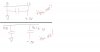
Attachments
Last edited: