vloschiavo
New Member
First thank you for any assistance with this as I am a complete newbie to electrical engineering with some physics background.
I have built a few of Adafruit's Mintyboosts for friends (Minty Boost! - USB charger for your gadgets) and have been mostly satisfied with their performance. The only issue I have with the design is the limitation of 500mA output. With the newer phones and other gadgetry that can be charged via USB (think tablets, video cameras, etc) this 500mA output results in a painfully slow charge for those larger capacity devices.
Since Lithium and LiFePO4 batteries have, in general, a lower internal resistance and greater charge and discharge current capabilities, these make a great starting point for the charging current source. Pre-made/pre-packaged Li-Ion chargers are fairly cheap and readily available so this making re-charging these fairly straight forward; no need to worry about slow start, constant current, constant voltage charging modes for Li-Ion as the charger takes care of things. I'm using this charger (USB LiIon/LiPoly charger [v1.1] ID: 259 - $10.00 : Adafruit Industries, Unique & fun DIY electronics and kits), I simply replaced a single resistor to increase it's charge rate to 1Amp, with the battery I'm using, this putts me well below the "safe" 1C charge rate at about 1/5C. A thermistor can also be added for additional safety.
So, I've taken the MightyMintyBoost (How to make a solar iPod/iPhone charger -aka MightyMintyBoost) (by Honus (Instructables Member: Honus)) a step further. Utilizing larger capacity Li-Ion Cells (with low voltage, high voltage, and high current protection built in) I can easily put out 1 Amp to a Step-Up circuit.
I would prefer to simply purchase something that will accept between 2-4.5VDC in and output 5VDC 1-2ampls. As I wasn't able to find something like this (https://www.electro-tech-online.com/custompdfs/2010/12/fx55plug.pdf) that is still in production or for sale somewhere, I decided to try and build my own.
I prototyped the following 5V/1A Boost Converter on a solderless breadboard based on the MAX1771 (https://www.electro-tech-online.com/custompdfs/2010/12/MAX1771.pdf) chip. See schematic in figure 9 on page 16 of the datasheet. The circuit "works" in that it will provide a 5.05V open circuit, but I get significant voltage sag under load, almost 0.9VDC. Additionally, the maximum output current I can draw seems to be less than 300mA.
This is where my lack of knowledge is hindering my troubleshooting ability. However, I believe the problem may lie in one or more of the following:
1) Breadboard resistance and inductance? Will I see better performance (less voltage sag and more current) on a PCB or perfboard?
2) Physical circuit layout? How do I figure out how to improve the layout? Recommendations on reading material?
3) Power MOSFET Substitution: I was unable to locate the MOSFET indicated "MTD20N03HDL" and substituted with the following: https://www.electro-tech-online.com/custompdfs/2010/12/IRL630PBF-Vishay-datasheet-8625071.pdf
a. I think I should be concerned with the RDS as the original MOSFET specifies 35mΩ and the replacement is 40mΩ.
b. Other? Switching speed coupled with inductor?
4) Inductor Substitution not keeping up with current demands: I chose this 220uH inductor RLB9012-221KL. (https://www.electro-tech-online.com/custompdfs/2010/12/RLB9012.pdf)
a. From what I've read, this seems to be sufficient for a 1 amp output
b. Plus it's Test Freq is rated at 796kHz - which is below the Max1771's output (300kHz switching output).
5) Internal resistance of the circuit due to alligator clips across diode: Since the diode's axial leads are way too thick for the breadboard, I had to use alligator clips to get it in circuit without soldering it.
Questions:
1) Does anyone know of or can you find a prebuilt DC-DC step up that I can just purchase that fits the 2-4.5VDC in and 5VDC out >=1 amp requirements?
2) Thoughts on troubleshooting the circuit?
Thank you,
Vince
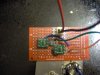
ps. Here is a pic of the circuit:
**broken link removed**
I have built a few of Adafruit's Mintyboosts for friends (Minty Boost! - USB charger for your gadgets) and have been mostly satisfied with their performance. The only issue I have with the design is the limitation of 500mA output. With the newer phones and other gadgetry that can be charged via USB (think tablets, video cameras, etc) this 500mA output results in a painfully slow charge for those larger capacity devices.
Since Lithium and LiFePO4 batteries have, in general, a lower internal resistance and greater charge and discharge current capabilities, these make a great starting point for the charging current source. Pre-made/pre-packaged Li-Ion chargers are fairly cheap and readily available so this making re-charging these fairly straight forward; no need to worry about slow start, constant current, constant voltage charging modes for Li-Ion as the charger takes care of things. I'm using this charger (USB LiIon/LiPoly charger [v1.1] ID: 259 - $10.00 : Adafruit Industries, Unique & fun DIY electronics and kits), I simply replaced a single resistor to increase it's charge rate to 1Amp, with the battery I'm using, this putts me well below the "safe" 1C charge rate at about 1/5C. A thermistor can also be added for additional safety.
So, I've taken the MightyMintyBoost (How to make a solar iPod/iPhone charger -aka MightyMintyBoost) (by Honus (Instructables Member: Honus)) a step further. Utilizing larger capacity Li-Ion Cells (with low voltage, high voltage, and high current protection built in) I can easily put out 1 Amp to a Step-Up circuit.
I would prefer to simply purchase something that will accept between 2-4.5VDC in and output 5VDC 1-2ampls. As I wasn't able to find something like this (https://www.electro-tech-online.com/custompdfs/2010/12/fx55plug.pdf) that is still in production or for sale somewhere, I decided to try and build my own.
I prototyped the following 5V/1A Boost Converter on a solderless breadboard based on the MAX1771 (https://www.electro-tech-online.com/custompdfs/2010/12/MAX1771.pdf) chip. See schematic in figure 9 on page 16 of the datasheet. The circuit "works" in that it will provide a 5.05V open circuit, but I get significant voltage sag under load, almost 0.9VDC. Additionally, the maximum output current I can draw seems to be less than 300mA.
This is where my lack of knowledge is hindering my troubleshooting ability. However, I believe the problem may lie in one or more of the following:
1) Breadboard resistance and inductance? Will I see better performance (less voltage sag and more current) on a PCB or perfboard?
2) Physical circuit layout? How do I figure out how to improve the layout? Recommendations on reading material?
3) Power MOSFET Substitution: I was unable to locate the MOSFET indicated "MTD20N03HDL" and substituted with the following: https://www.electro-tech-online.com/custompdfs/2010/12/IRL630PBF-Vishay-datasheet-8625071.pdf
a. I think I should be concerned with the RDS as the original MOSFET specifies 35mΩ and the replacement is 40mΩ.
b. Other? Switching speed coupled with inductor?
4) Inductor Substitution not keeping up with current demands: I chose this 220uH inductor RLB9012-221KL. (https://www.electro-tech-online.com/custompdfs/2010/12/RLB9012.pdf)
a. From what I've read, this seems to be sufficient for a 1 amp output
b. Plus it's Test Freq is rated at 796kHz - which is below the Max1771's output (300kHz switching output).
5) Internal resistance of the circuit due to alligator clips across diode: Since the diode's axial leads are way too thick for the breadboard, I had to use alligator clips to get it in circuit without soldering it.
Questions:
1) Does anyone know of or can you find a prebuilt DC-DC step up that I can just purchase that fits the 2-4.5VDC in and 5VDC out >=1 amp requirements?
2) Thoughts on troubleshooting the circuit?
Thank you,
Vince
ps. Here is a pic of the circuit:
**broken link removed**
") - I've ordered a more appropriate inductor and N-FET.
- I've ordered a more appropriate inductor and N-FET. 