Continue to Site

Welcome to our site!

Electro Tech is an online community (with over 170,000 members) who enjoy talking about and building electronic circuits, projects and gadgets. To participate you need to register. Registration is free. Click here to register now.

  • Welcome to our site! Electro Tech is an online community (with over 170,000 members) who enjoy talking about and building electronic circuits, projects and gadgets. To participate you need to register. Registration is free. Click here to register now.

19V DC to 12V AC

Status
Not open for further replies.

TheGuy

New Member
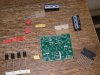
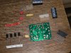
Hi, I've just got an amplifier kit from Velleman for an audio project of mine. On the outer box it failed to mention that it requires 12V AC, not 12V DC as I had presumed.

I wanted to run the thing from a 19V DC source. Is it simple to make a circuit to convert it to what's required? I'm pretty stuck otherwise.


Thanks for any help.
 
It's pretty complicated to turn DC into AC. It involves switching a DC square wave and varying the duty cycle sinusoidally and then filtering out the high frequency square waves leaving only the low frequency fundamental sine-wave. You could go see if you can't find an DC-AC inverter to buy...might be able to find a small one that runs off 19V.

But the amplifier probably runs off DC and if you know what you're looking at you can bypass the 12V AC regulator part so you can directly inject some DC in.
 
Last edited:
It's pretty complicated to turn DC into AC. It involves switching a DC square wave and varying the duty cycle sinusoidally and then filtering out the high frequency square waves leaving only the low frequency fundamental sine-wave. You could go see if you can't find an DC-AC inverter to buy...might be able to find a small one that runs off 19V.

Ah, not what I was hoping to hear.

But the amplifier probably runs off DC and if you know what you're looking at you can bypass the 12V AC regulator part so you can directly inject some DC in.

It looks to me like it can be bypassed, but I'm no expert! Do you think you could take a look at the images I've attached? It's a simple circuit, but I'm not very good at electronics so I don't really know what does what. I really hope it's possible to power it with DC!
 

Attachments

  • P1390085.JPG
    P1390085.JPG
    1.4 MB · Views: 679
  • P1390086.JPG
    P1390086.JPG
    1.5 MB · Views: 1,005
Last edited:
OK, buy a DC wall wart and make an inverter for that.

I thought (incorrectly) the problem was "how to get the circuit to work".
 
Doing this from 19 VDC would not be easy as covered. There are other options and among them is an AC wall wart. All wall warts are not all or always DC output. Many like several of these including the sta-4112A are AC output. Available from Mouser and just about anywhere. You could also buy a 120 VAC to 12 VAC transformer at Radio Shack or anywhere else.

Now it looks to me like they just take the 12 VAC and run it through a full wave bridge (D1, D2, D3 & D4) to get 12 VDC they pass along to the two caps as filters. If that is true you could get a LM7812 12 volt regulator and feed it the 19 VDC you have. The LM7812 regulator can be had at Radio Shack or just about anywhere. Now omit the diodes in the build and at the junctions of the diodes where two cathodes (band sides) and the two anodes (non band sides) tie together apply your 12 VDC output from your LM7812 with the common (NEG) going to where the anodes would have been tied and the + out of the regulator to where the cathode (band) junctions. That should work fine.

Ron
 
Last edited:
please check the download from here of the illustrated assembly amaual.
**broken link removed**

i feel the kit is K4003_rev1
it employes 12-0-12 transformer and thus dual voltages are needed
perhaps the cheapest is a salvaged transformer with 12-0-12 AC and 2 amps load capacity.
otherwise you need to make a dc to dc converter to the same spec. But direct use or regulated use of 19V to 12 V wont work.
I know deriving 9.5 and -9.5 from the 19V DC by use of Op-amp, but it may not help delivering load.i have the datasheet document as a download. but whether we are permitted to upload, is an issue.
 
Last edited:
If you look at page 8 and page 11 of http://www.vellemanusa.com/downloads/0/illustrated/illustrated_assembly_manual_k4003_rev1.pdf
You will see that you can run it from two 12 V batteries. You need a + and - supply.
You could use a voltage divider to give you the mid point of the 19 V, but that couldn't just be two resistors. It would need transistor buffers to give the current that you would need without excessive power consumption. Also the voltage would end up too low at +/- 9.5 V.

You could use an inverting buck/boost supply, like the second diagram on page 21 of **broken link removed** to give you -19 V or so from your present +19 V, and then run the circuit from +/- 19 V. If it is designed to run from 12 V ac, the peak is about 17 V anyhow, so 19 V shouldn't matter.

Where are you getting the 19 V from?
 
again we are trying to go back to 12V AC. We need 12-0 -12 AC to be able to get the voltage and at a load current of 2 amps.
 
again we are trying to go back to 12V AC. We need 12-0 -12 AC to be able to get the voltage and at a load current of 2 amps.

Uh Oh, and my bad earlier. Never saw the manual and caught the CT on the AC so it uses a split (+/-) supply. Also never saw the heat sink before. Yep, I would just buy a 24 VAC CT transformer (12-0-12) as suggested. Also since they call out 15 watts RMS I would look for a 2 amp transformer. Thanks Sarma for the link.

Ron
 
Now it looks to me like they just take the 12 VAC and run it through a full wave bridge (D1, D2, D3 & D4) to get 12 VDC they pass along to the two caps as filters. If that is true you could get a LM7812 12 volt regulator and feed it the 19 VDC you have. The LM7812 regulator can be had at Radio Shack or just about anywhere. Now omit the diodes in the build and at the junctions of the diodes where two cathodes (band sides) and the two anodes (non band sides) tie together apply your 12 VDC output from your LM7812 with the common (NEG) going to where the anodes would have been tied and the + out of the regulator to where the cathode (band) junctions. That should work fine.

This sounds good, if it will work. So passing it through the LM7812 would basically reduce the voltage from 19 VDC to 12 VDC? If that's the case, I could then try it with another power supply, just to check that it works.

In the manual it says that an "additional rectifier and smoothing filter are unnecessary, as alternating current can be directly connected to the unit". Does this mean that it's not as simple as just connecting DC? Wouldn't I have to build a rectifier and smoothing filter?

Thanks for the help so far!

No, my thought won't work. After seeing the diagram they are using 24 VAC center tapped for 12-0-12. I posted a my bad as to that idea. However, you can likely get a transformer from Radio Shack and use it to power the amp. Also I see where it is capable of 15 Watts RMS so you want about a 2 amp source. The Sarma posted was the big help.

Back to this won't be easy or practical from 19 VDC.

Ron
 
Last edited:
No, my thought won't work. After seeing the diagram they are using 24 VAC center tapped for 12-0-12. I posted a my bad as to that idea. However, you can likely get a transformer from Radio Shack and use it to power the amp. Also I see where it is capable of 15 Watts RMS so you want about a 2 amp source. The Sarma posted was the big help.

Back to this won't be easy or practical from 19 VDC.

Ron

Okay, thanks for the help anyway! I'll have a look around for a transformer, but it's likely that I'll take the kit back for a refund (as it didn't say on the box that it was AC).

I'll probably end up building one from scratch to suit my needs. Are there any amplifier circuits that you would recommend?
 
Maybe using an amplifier similar to this one that uses a single supply. This isn't my forte but the person in these forums who has a handle on this stuff is AudioGuru. I am sure he would have some valid suggestions. You may want to start a new thread seeking his assistance. The chip I linked to is mono so you would need two identical circuits for stereo. Working from 19 VDC makes things difficult and for the power you were looking at you would want about 2 amps. Let's hope Audio Guru sees this thread or just start a new thread and reference this one. Use Audio Amp in the title as it will likely catch his eye. :)

You are looking for something along the lines of an automotive stereo amp and we still need to get that 19 VDC down to about 14.5 VDC give or take a little.

Ron
 
Status
Not open for further replies.

New Articles From Microcontroller Tips

Back
Top