Continue to Site

Welcome to our site!

Electro Tech is an online community (with over 170,000 members) who enjoy talking about and building electronic circuits, projects and gadgets. To participate you need to register. Registration is free. Click here to register now.

  • Welcome to our site! Electro Tech is an online community (with over 170,000 members) who enjoy talking about and building electronic circuits, projects and gadgets. To participate you need to register. Registration is free. Click here to register now.

18v AC/5v DC Power Supply

Status
Not open for further replies.

angie1199

New Member
Hi all,

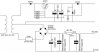
New to electronics but need a power supply to supply 18v AC and 5v DC. It's got to give enough power for up to 50 2.5v 30mA LEDs on the 5v DC out and enough to the 18v AC to charge a capacitor discharge unit.

I have no idea how much current the capacitor discharge unit requires.

Below is a 5v DC circuit diagram I found on the web and redrew adding the 18v AC spur.

So here's my problem.

1. How do I work out what VA I require ???
2. Will this spur addition work or do I find a two output transformer ???

Angie
 

Attachments

  • PS_Diagram.jpg
    PS_Diagram.jpg
    34.1 KB · Views: 897
You need to figure out how much current you need for your "capacitor discharge unit" - they will look like short circuits when discharged on startup so you will also require potentially allowing a large inrush current. Make sure your fuse can accomodate that. This applies whether or not you use a one output or dual output transformer. The find the proper VA ratings, you will need to work out what kind of a load that capacitor discharge unit will look like. Your 5V load is much more straightforward.
 
It say maximum 2.5 Amps for the CDU on a webpage that sells the circuit (I just found that).

The capacitors are 2200uf (whatever that is) and 35v
Theres a BD 909 IC on the board and I have no idea what that is either.
There's also one resistor (looks like green/blue/brown/gold = (512R with 5% tolerance) and two diodes that I can't read the values.

I assume from this I need the AC out to be at 2.5A... is that right?

If so VA = 2.5 * 18v = 45VA?

Angie
 
angie1199 said:
It say maximum 2.5 Amps for the CDU on a webpage that sells the circuit (I just found that).

The capacitors are 2200uf (whatever that is) and 35v
Theres a BD 909 IC on the board and I have no idea what that is either.
There's also one resistor (looks like green/blue/brown/gold = (512R with 5% tolerance) and two diodes that I can't read the values.

I assume from this I need the AC out to be at 2.5A... is that right?

If so VA = 2.5 * 18v = 45VA?

Angie

Well, you gonna need 45W, because U*i is power, not apparent power.
VA = W/PF.
Assuming a PF aroud 0,65
VA = 45/0,65 =~ 70VA.

By your schematic, increase the value of the filter capacitor, 470uF is too low. 2200uF or 3000uF are good values.
BD909 is a NPN power transistor, probably is used to regulate the output.
The resistor is not 512R, because Green-Blue-Brown is 560R, probably is used to bias the BD909.
The diodes should be zeners, to regulate the output, together with the transistor.
 
Ok, assume I'm an electronics newbie...

What's a PF, what are the U and i in the power formula and how does this differ from apparent power (whatever that is).

You say increase the filter capacitor. What is uF? I understand that this might seem basic, but I 'am' a newbie.

And yes, the BD909 is a NPN power transistor to regulate the output.

I do learn quick if I get idiot proof answers :)

thanks
Angie
 
angie1199 said:
Ok, assume I'm an electronics newbie...

Is this an assumption? If it is true, for your safety, I recommend that you do not work on a project connecting to mains. It can be fatal unless you really know what you are doing. IF you are working out the design and having someone more experienced build it then that's another matter.

If you are going to do it anyways, at least do not work on it alone.
 
It appears that 'PF" refers to power factor. Alternating current into a purely resistive load allows the voltage and current to remain in synch or results in no lead or lag between voltage peaks and current peaks. If the load is inductive or capacitive in nature then the voltage peaks and current peaks do not occur at the same time - power factor describes this. A power factor of 1 suggests a purely resistive load - and drops toward zero as the load becomes more reactive (capacitance or inductance).

In electronics 'pf' can refer to picofarad. That wasn't used so far in this posting but will come up eventually.
 
Unless I am mistaken, there appear to be two requirements - for an 18 vac source for a CDU (not sure what that does) and for a 5 vdc supply to power 50-30 ma LEDs.

The circuit for the 5 vdc supply shows a 470 microfarad capacitor prior to what might be a 3 terminal regulator (7805 maybe). It's possible that the ripple reduction of the regulator and the not too stringent requirements of the LEDs may be such that the 470 microfarad capacitor is good enough. You make no mention of ripple - and it may be a non-issue here. A reason not to go to a bigger capacitor is mentioned here - the current to charge the capacitor may blow a fuse.
 
stevez said:
It appears that 'PF" refers to power factor. Alternating current into a purely resistive load allows the voltage and current to remain in synch or results in no lead or lag between voltage peaks and current peaks. If the load is inductive or capacitive in nature then the voltage peaks and current peaks do not occur at the same time - power factor describes this. A power factor of 1 suggests a purely resistive load - and drops toward zero as the load becomes more reactive (capacitance or inductance).

In electronics 'pf' can refer to picofarad. That wasn't used so far in this posting but will come up eventually.

Thanks, Stevez.
That PF was a Power Factor one. Sorry, I forgot the punctuation (P.F.).

Angie,
Well,
P = U*i
P = power, in watts.
U = voltage (difference of potencial), in volts
i = current, in ampères.

Like stevez said, if you are going to use leds in the 5V supply, you won't need any big filter capacitor. In fact, you won't need them (if you are going to turn leds, only).
uF means microfarad, or, 0.000001 farad.


This is for everyone:

We have to pay attention to capital letters. I don't want to be that kind of annoying guy, but the capitalization makes the difference, always.
pF = picofarad.
pf = pico-something.

mA = miliampères. (0.001 A)
MA = megampères. (1000000A)

mb = milibits
mB = milibytes
Mb = megabits
MB = megabytes
 
You are absolutely correct about the importance of capital letters. Still, I find it helpful in some situations to make a statement that verifies what I think I mean - or what I think they mean. It seems a month or so ago I got tripped up on milli and mega with someone - once we cleared that up communication was easier.

I've been around the technical world a while. It does help to be brief but precise to keep everyone on the same page. Implied in that is say exactly what you mean and only say it once, as simply as possible. With that said, I've learned that restating something a bit differently - or being a bit more wordy - has turned up some rather startling discrepancies in communication or understanding.
 
Stevez,

You said "Unless I am mistaken, there appear to be two requirements - for an 18 vac source for a CDU (not sure what that does) and for a 5 vdc supply to power 50-30 ma LEDs."

Yep. So I have a capacitor discharge unit (as seen **broken link removed**) which apparently requires 2.5A.

50 LEDs @ 30mA = 1.5A

So I need 4A current.

If I used a 0-20 0-20V 50VA MIN CHASSIS Transformer would that be good..... or bad?
 
Hayato said:
We have to pay attention to capital letters. I don't want to be that kind of annoying guy, but the capitalization makes the difference, always.
pF = picofarad.
pf = pico-something.

mA = miliampères. (0.001 A)
MA = megampères. (1000000A)

mb = milibits
mB = milibytes
Mb = megabits
MB = megabytes

hmm, In 30 years of developing systems software, I've never seen miliBits or milliBytes used - not sure what exactly 1/1000th of a bit or byte is, anyway. maybe in communications theory or something. kind of obscure. I always assume mB is megabytes. caps is correct, though. mb would get a blank stare.

pf vs pF - what is the something that pf is used for? I've never seen it and have always assumes one means pF when they write pf.

MA also means Massachusetts
 
philba said:
hmm, In 30 years of developing systems software, I've never seen miliBits or milliBytes used - not sure what exactly 1/1000th of a bit or byte is, anyway. maybe in communications theory or something. kind of obscure. I always assume mB is megabytes. caps is correct, though. mb would get a blank stare.

pf vs pF - what is the something that pf is used for? I've never seen it and have always assumes one means pF when they write pf.

MA also means Massachusetts

Hello, yes there is no such things like milibits or milibytes. I just exposed a common mistake.

Yes, MA is Massachusetts, but we have to see the context, when we are talking about electronics it's obvious that MA is not Massachusetts, when I say: :D
The Energy Company has a transformer capable to handle 220V at 1 MA.
 
The minimum quantity of data is 1 bit, you can't have any less than that.
 
All the CDUs I've seen are powered by the 12V car battery,I assume it is a car engine ignition device. The led array requires about 15 mA per diode and about 1.2 V ,I'm working from memory but I think that's correct.
 
Hero999 said:
The minimum quantity of data is 1 bit, you can't have any less than that.


Like most computers mine came with Microsoft now if I want to change to another OS how do I go about it,do I have to wipe my hard drive clean and being a beginner what major problems am i likely to meet.
 
I've added an updated diagram which hopefully will get me the answer to my problem. This is now the full circuits, the regulated 5v DC and the 18v AC to 18v DC half wave.If as the diagram says I use a 18v AC - 18v AC 20VA transformer how many amps will it allow before meltdown please?

oldtimer said:
Like most computers mine came with Microsoft now if I want to change to another OS how do I go about it,do I have to wipe my hard drive clean and being a beginner what major problems am i likely to meet.

You could install a second hard drive and have a dual boot system. Or partition the hard drive you have to two partitions (supposing it's big enough) and install the other O/S on the second partition.

As for your documents, Back them up first!!!!!!!! I've had to reclaim data from too many customers computers in the past... It costs money if you don't have a backup!

If you're putting Linux in there are a number of apps that will allow you to open some documents originally from the MS O/S.

Also check that all the drivers you need for graphics card, modem, network card etc. are available for the new O/S. If they're not then chances are you won't get your peripherals to work. You should have disks with each device that may have the drivers on them.
 
The 2.5 amp load at 0.65 power factor and 20 volts (that's what you'll be delivering) is 77 VA. The 1.5 amp load is 46 VA. The challenge - is the load continuous? If it is the answer is easy - if not and you want to get by with a smaller transformer you'll need to determine the load based on the expected operation of the circuit. Note that you can reduce the 46 VA part by going to a switching supply as it is more efficient.
 
Status
Not open for further replies.

New Articles From Microcontroller Tips

Back
Top