Electro Tech is an online community (with over 170,000 members) who enjoy talking about and building electronic circuits, projects and gadgets. To participate you need to register. Registration is free. Click here to register now.
Welcome to our site! Electro Tech is an online community (with over 170,000 members) who enjoy talking about and building electronic circuits, projects and gadgets. To participate you need to register. Registration is free. Click here to register now.
Yes, any of them will do so - the 12C508 series and others have a calibration byte which makes them more than accurate enough at 9600 baud. But even the 16F628 (which doesn't have a calibration byte) runs 9600 quite happily using the internal oscillator.
Bit banged or not makes no difference anyway, the UART runs from the same oscillator!.
The little 8-pin 12F683 sports a 1% tolerance 8-MHz INTOSC and you can find 9600 baud full-duplex and half-duplex demo programs at this Forum Microchip thread;
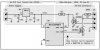
Cool schematic, I've never seen 2N7000s used as the buffer. I usually use a DS275. Question, why bother to invert a bit bashed port? I would normally just use 22K resistors.
PS Mike, I read your code for an 8 MHz clock, I wonder what the maximum baud rate with a 32.768 kHz crystal would be?
Yes Mike, RTS is is used to pull-up the open-drain... Yes, this circuit works well with 3-volt PICs... Here's a "working" 3-volt circuit... <added> Oops, sorry, it's a 3.3-volt circuit (grin)...
You have not made the source/object codes of your projects public so I assume, at this very moment, that money is involved for providing them. You have absolute right to choose not disclosing them.
Would you paid for intellectual properties of design by others if you get paid for selling Kits which use that design?
I'm still working on the source codes. They will be free for
They will be available to anyone free for non commercial use.
The code is mostly fragmented on all the projects, but will be released when available.
I was hoping to make these all community projects, and the only money if any would be made by selling the PCB boards or kits.
Commercial vendors would have to licence the design.I'm hoping for a GNU type model.
Many of my devices were designed for practial use and some for fun (Snake, Owl, Zebra)
The Cricket was something I wanted to take commercial to compete with more expensive (and I wanted more control) commercial communicating thermostats like OmniStat, RCS & Aprilaire. But going commercial was going to cast $$$$$ so instead of putting it on shelf I'm making it open source for both the hardware including PCB layout gotta learn Eagle and software. I belive a community effort will benifit everyone.
All the commercial thermostats were inflexable in design, some have bugs (my Aprilaire is easy to lockup when communicating) so I went about designing my own. It's was originally much more complex and took many many different designs to get to the very simple one it is now.
Originally it included 6 relays to be like the Aprilaire, but I later split this into a seperate device the Ladybug.
So when the RS485 Cricket is combined with the Ladybug you have a 6 relay zoned system with RS232 control. You can add more Crickets, Ladybugs, Emu (designed for Curtain / Register control)
And control the whole thing from something as simple as a Rabbit **broken link removed**
(I'm putting up Hossenfeffer soon a Rabbit 37x0 to RS485 / RS232 MAX3160) or a windows or linux box) I have a 24/7 linux gateway running for music, web, email etc.
I'm more than happy to share the source code when available, I've only had my site up for a week and it's taken so much time just to get it looking right. Code snippits will be posted and daily updates will be posted (like www.slimdevices.com does)
This site uses cookies to help personalise content, tailor your experience and to keep you logged in if you register.
By continuing to use this site, you are consenting to our use of cookies.