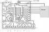
Can someone one out there take a look at this PCB layout. I have redrawn all my PIC board layouts this year to include a voltage regulator so as to run 9& 12v motors from the same supply as the PIC. I have connected up a 12v stepper to a 28 pin board as on the layout and after blowing a couple of pics checked the voltage going to the pic and as soon as motor starts to run the voltage jumps from 5 to 12 blowing the pic, how can this be? The supply to the pic is after the regulator, how can the 12v for the stepper be getting to the PIC. Any advice gratefully received
Thanks
Tony
Thanks
Tony