Electro Tech is an online community (with over 170,000 members) who enjoy talking about and building electronic circuits, projects and gadgets. To participate you need to register. Registration is free. Click here to register now.
Welcome to our site! Electro Tech is an online community (with over 170,000 members) who enjoy talking about and building electronic circuits, projects and gadgets. To participate you need to register. Registration is free. Click here to register now.
Here is a schematic of a power supply that should deliver 3A of current at 12V DC with very little noise.You were not clear on what kind of regulator you wanted or what what features you wanted the power supply to have so I just put several in and you can remove what you don't want.Starting with the input the fuse (F1) is not completely necesary and can be left out if you wish along with the blown fuse indicator (R1, C1, D1, D2). If the fuse is used try to keep it on the Hot line for proper protection. The varistors that are in the schematic are to prevent power serges and can also be left out if their protection is not needed. The input labeled ground is earth ground and if the varistors are used they both need to have at least one lead connected to ground.The transformer is nothing special, 240V RMS in, 15V RMS out (yes it has to be 15V other wise the regulators will experience ripple)On the transformers output, I assumed your signal frequency was 50Hz and the filter capacitors were designed with that assumption in mind, if you are using a 60Hz signal then that is even better and you will have less noise on the output.The bridge rectifier is a 4A type bridge and should have no problems with handeling your current demands.Since you did not specify what type of regulator you wanted, I took the liberty of designing 4 different ones that you can use. Regulator 1 is the most complex and will also have the lowest output noise. U1 does not need to be a 741, there are plenty of better op-amps out there as long as its voltage supply can handel the input voltage (about 21.5V peak) Q1 is not specified so you should try to find one that can handle at least 25V CE voltage and 4A CE current. I personaly would use a 2N3055 transistor but it is a bit overkill.Regulator 2 will also be very well suited to handle your power needs but it will only output 3A and no more (if you are drawing 3A continusly you may want to consider a sizeable heat sink)Regulator 3 is fairly simple to make and will give you the best trade off between voltage ripple and simplicity. The rule for Q2 is the same as Q1.Regulator 4 is the simplest but will also have a fair amount of output noise. The same rule applies to Q3 as Q1 and Q2.If you experience a lot of noise in the circuit, try adding another 100nF capacitor to the output of the bridge rectifier. If that does not help, add one to the output of the transformer (this means that the noise is coming from the primary line). The filter capacitors should be able to supply up to 3.5A of current without any noticeable noise.Sorry for the inconvinece, but I am working with a very slow computer that can't even remember it's name, so just go ahead and copy and past the link, if it does not work I will try again later.**broken link removed**
#1: The current that the 741 can source is quite low, ~5mA. 5mA times the Hfe of the transistor (~50) means its collector current will be only ~250mA, so it is a whimpy regulator. Another problem is that the 741 will only pull to ~5V less than the unregulated input (its own v+ pin), so you have created a regulator with a drop-out voltage greater than 5V, so the regulator transistor will run hot.
#2: needs some provision to cause the regulators to share the current equally, otherwise the one with the slightly higher output will do all the work until it goes into thermal shutdown, and then #2 will take the load (at a slightly lower output voltage) it will go into thermal shutdown, and finally so will the third...
#3: the external pass transistor is not inside the regulator's feedback loop, so will have crummy voltage regulation, and will only put out ~11.2V The correct way of putting an external pass transistor around a 7812 is shown on the data sheet. Hint: it uses a PNP transistor.
#4: is not a active regulator; just an emitter follower sort of like #3. The 1K dropping resistor cannot supply enough current to the base of the pass transistor, sort of like #1.
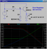
For details, look at the LtSpice sim, below.
None of these will output anywhere close to 3A!
Not trying to beat you up, but I used to grade student projects... (and have built ~100 linear power supplies).
I used a 741 in the design because I didn't want to spend an hour and a half looking for a different op-amp, I specificly said that it can be switched out with a different op-amp for a higher quality signal. Second, the filter capacitors were calculated with so that their voltage will not drop below the 5V threshold at 50Hz, a 60Hz signal will be better because then the voltage will be higher and the regulators will be less likely to stop regulating.I took what you said about regulator 2 and went out to radio shack and bouch all the regulators they had in stock (that's $10 of wasted money I'll never get back) connected them the way I suggested and had a 3A load on. Even though each regulator had a slightly different output, the high load caused that to quickly drop so that they were all equal and when the current out of each was measured, came out to be 1A not one op-amp went into thermal shut down and they continued to supply the load for an hour before they final overheated as a group (very small heat sinks were attached).Number 3 and number 4 were not intended to be high quality regulators and were only included if the OP wanted a simple solution. However I do have a regulator just like number 4 in a radio of mine that is regulating 36V to 18V and it is used to charge the batteries of the radio and also to power the rest of the circuit if the other regulators get too hot (their input is switched from 36V to the 18V untill they cool). But you are right in the fact that it does have a fairly high output ripple. (I did say it was the lowest quality regulator)
This site uses cookies to help personalise content, tailor your experience and to keep you logged in if you register.
By continuing to use this site, you are consenting to our use of cookies.

")