Continue to Site

Welcome to our site!

Electro Tech is an online community (with over 170,000 members) who enjoy talking about and building electronic circuits, projects and gadgets. To participate you need to register. Registration is free. Click here to register now.

  • Welcome to our site! Electro Tech is an online community (with over 170,000 members) who enjoy talking about and building electronic circuits, projects and gadgets. To participate you need to register. Registration is free. Click here to register now.

12v Lead Acid Charger, LM317 Question

Status
Not open for further replies.

joecool85

Member
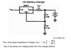
I found a schematic on the LM317 datasheet (attatched). How does Rs limit current? I'd like to use this to charge my motorcycle batteries (7AH and 12AH), not at the same time. Will it work alright? It'd be powered by an 18v 680ma DC output walwart.

Right now I charge the battery with a 12v 100ma DC output walwart, it takes a few days but it does charge it. But I'd like a little voltage protection (the 100ma 12v is 15.51v with no load, so I'm sure eventually it could get the battery there), and also 100ma just takes forever to charge a battery. 680ma would get it charged in less than 24 hours.
 

Attachments

  • Picture 1.png
    Picture 1.png
    27.9 KB · Views: 6,102
Last edited:
Yes, that will do it. Rs makes the charger look like it is driving the charger through a resistor (2.2Ω) that's bigger than the one in the circuit (.2Ω) by the formula at the bottom. With those values it should put out about 13.75V, so you have voltage and a certain amount of current limiting.

How discharged does your battery typically get?
 
Last edited:
How much would that limit the current then? I'm not really worried about limiting the current as it can't go beyond 680ma anyway. Is it possible to damage a 7A 12v battery by holding it at 13.7v @ 680ma after it is fully charged?

Normally the battery doesn't need a whole lot of charging, just top it off mid winter and then before the season starts to keep it fresh. It probably gets down to 80% before I charge it. Although there was once or twice I've needed to charge it up from 0% charge...once was an electrical short, the other was when I was trouble shooting and I kept cranking on the electric starter. After an afternoon of the bike not starting, the battery wouldn't even crank the engine at all.
 
The current will be zero when it hits 13.75V, no problem there. This is a very good circuit for what you want. If it was deep discharged, there would be some issue with it taxing the wall transformer.
 
The current will be zero when it hits 13.75V, no problem there. This is a very good circuit for what you want. If it was deep discharged, there would be some issue with it taxing the wall transformer.

Why will the current be zero when it hits 13.75v? Is that due to Rs? What if it hits 13.75v before the battery is done charging?

Also, my 100ma transformer charged it fine...it took half a week, but it did it. So could I just leave out Rs then since it doesn't need any current regulation? Also, what wattage resistors should I use?
 
Last edited:
>>Why will the current be zero when it hits 13.75v?

When the battery's internal voltage hits 13.75V there will be no differential between the charger and the battery, so no current. If you check the unloaded float voltage of that lead acid battery, fully charged and disconnected from anything, I believe you will find it's over 13V. 13.75 is an excellent choice for the charge point voltage.

>>What if it hits 13.75v before the battery is done charging?

It's normal to see the charger at full voltage across a battery that hasn't REALLY finished charging. To do that, you need to measure the current.

>>Is that due to Rs?
>>Also, what wattage resistors should I use?

Rs just makes the LM317 appear to have a 2.2ohm power resistor in series with it. Incredibly, with a maximum output of .68A, all those resistors can be quarter-watt. But use a 1 watt for Rs, a really drained battery might just pull more more current.

>>So could I just leave out Rs then since it doesn't need any current regulation?

Probably. The battery can easily handle more current, Rs is mainly in there to reduce the load on the LM317 when it's dealing with a heavily discharged battery. It DOES have some internal protection against over temperature (high wattage). Help it out and give it a good heatsink, this is a series-pass regulator. The wallwart will almost certainly put out more current than 680ma if the voltage is loaded to under 12V. Try hooking an ammeter (on a high setting) in series with the wallwart and a heavy load (a headlight or something). See how much it can REALLY put out. THat's what the regulator is going to have to deal with
 
Last edited:
So if I put a large heatsink on the chip, it should be fine without Rs? And I can use standard 1/4w resistors then for the R1 and R2.

Sounds good to me.
 
Use a heatsink either way. Rs isn't really necessary. R1 and R2 can be 1/4w.
 
If you want to make it safe (including overcharge protection) you're better off using a UC3906 lead-acid-battery charger IC.

You can kill any battery easily overcharging it.

Boncuk
 
If you want to make it safe (including overcharge protection) you're better off using a UC3906 lead-acid-battery charger IC.

You can kill any battery easily overcharging it.

Boncuk

I'm not worried about overcharging. The charge will happen slow enough that it won't just randomly explode, and I'm normally impatient and check all the time to see how it's coming along.

Also, limiting voltage to below gassing voltage (which is ~14.5v at room temp), will keep it from being dangerous. And as soon as the battery reaches the charger's voltage of 13.75v, it will no longer flow any current, keeping it from overcharging. That said, it could be slightly overcharged by the time it might hit 13.75v, but I doubt it and I'm not worried about it.
 
If I was wanting to limit it to 500ma output, what value would I use for Rs? Is that the Zout equation? If so, I get 0.22 with the stock values. Would that mean with 0.2 ohms at Rs it would put out 0.22 amps (220ma)?
 
The reason I'm looking for 500ma output is because I have a cheapy analog ($5-10 from walmart 8 years ago) multimeter that reads 500ma max, and I'd like to use it for this charger project. Would using the circuit as is with my 680ma wall mount transformer break my multimeter?
 
It might. You can use a pass resistor to change the scale of a cheap meter - look at the voltage developed across a .1 ohm resistor and the voltage will be 10x the current. In the circuit above you can simply read the voltage off the .2 ohm resistor.

That circuit doesn't really have current limiting, it just has a large apparent series resistance.

So if there is 1.25v across a 0.1 ohm resistor, there will be 12.5ma passing through it or 12.5 amps?
 
1.25v ÷ .1 Ω = 12.5 amps.
 
Ok, but since I will have a max of 680ma, that would only read as ~0.3v or so, my multimeter isn't at all that accurate. The lowest scale it has is 10v DC. I'd need voltage across the resistor to be a minimum of 1v before I'd be able to do it in this way.

I think it'd be easier to somehow lower my current in the circuit to 500ma. I know you can use a LM317 for current limiting, could I use one for current limiting and one for voltage regulation and have that work or would I lose too much voltage to be able to use my 18v 680ma transformer and still get 13.75v @ 500ma?
 
You can pick up a digital multimeter for less than $10 that reads millivolts.
 
You can pick up a digital multimeter for less than $10 that reads millivolts.

I could pick up a cheapy charger for $20. I was hoping I could get by with a LM317 or two and then I have everything else already (transformer, multimeter, battery clamps, case to house it in, heatsinks, caps, resistors, etc) and I'd only need to spend $5 or so. I could always do it without a meter and just check voltage and specific gravity of the battery to see when it's done charging, but it sure would be nice to have an ammeter on the circuit.

I'm tempted to just do it and see what happens (if it breaks the multimeter or not), if it does I can take the meter out of the circuit and/or figure something else out. Not sure if I want to go this route or not though, it would be nice if I could limit the circuit to 500ma.
 
The cheap charger probably won't have voltage regulation, it will just be a transformer and a rectifier. Spend a crummy sawbuck on a digital meter regardless.

Yes, you can put a LM317 configured as a current regulator ahead of a LM317 configured as a voltage regulator. They need a 1.25V drop minimum, and you have 18V to work with.

I thought I had read they needed a 3v drop, maybe that was for voltage regulation not current regulation?
 
Status
Not open for further replies.

Latest threads

Back
Top