Continue to Site

Welcome to our site!

Electro Tech is an online community (with over 170,000 members) who enjoy talking about and building electronic circuits, projects and gadgets. To participate you need to register. Registration is free. Click here to register now.

  • Welcome to our site! Electro Tech is an online community (with over 170,000 members) who enjoy talking about and building electronic circuits, projects and gadgets. To participate you need to register. Registration is free. Click here to register now.

12V Gel or Lead-Acid Charger Tweaking help needed

Status
Not open for further replies.

iONic

Member
My current understanding... correct me if I'm wrong.

Lead-Acid, including Gel Cells, both can be charged by the tenth rate method; that is, 1/10th the full power rating is used to charge the battery for 10 to 12hours. If we had a 32AHr battery we would charge it at 3.2A for 10 to 12 hours.

The idea of a trickle charger is that it can be left charging the battery continuously without fear of damage to the battery. To do this, the rate must be no more than 1/100th the power rating of the cell, and at least as high as the internal discharge rate of the cell. Thus If we had a 32AHr battery we would charge it at 320mA.

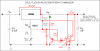
Therefore I need to alter the following circuit, from National Semiconductor, to do the following since I have both Lead-Acid and Gel Cells.

Given a 20V, 3A power source I would like to make a switchable charge-rate charger.

1) For Gel Cell(12V, 32AH) Initial charge current ~3A.
when the current falls below 320mA the charger switches to a lower "Float" Voltage(14.4) to prevent overcharging.

2) For Lead-Acid(12V, 32AH) Initial charge current of ~3A.
when the current falls below 320mA the charger switches to a lower "Float" Voltage(13.8) to prevent overcharging.

What would I have to do to make this dual circuit?

= = = = = = = = = = = = = = = = = = = = = = = = = = = = = = = = = = = = = = = = = = = = = = = = = = = = = = = = = = = = = = =
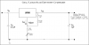
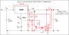
Here is a description of the working of the circuit according to Tony Van Roon:

his high-performance circuit first quickly starts (and holds) the charge at 2 amp, but as the voltage rises the current will consequently decrease.
When the current falls below 150mA, the charger automatically switches to a lower 'Float' voltage to prevent overcharging.
At the point that a full charge is reached, Q1 will bias and the LED will light.
The LM301A is a 8-pin OpAmp. Transistor Q1 is a PNP, Silicon, AF-Out type with a TO-39 metal case and can be substituted for a NTE or ECG129. Diode D1, a Si, GP Det. type, can be substituted with a NTE177 or ECG177. The LM350 (U1) needs to be cooled.
The input voltage should equal or about 18volts.

R1's function is to bleed some of the input voltage to the output and vice-versa. A 1N4002 or similar diode can be used also.
R2 and R5 are actually metal-film type resistors. To get the 3K for R2 use two 1K5 (1500 ohm) resistors in series. For R5 use two 470 ohm resistors in parallel. Or whatever combination to get to these values. For R1, 500 ohm, you can use two 1K in parallel or 470 + 33 ohms in series.
R7, the 0.2 ohm resistor, is a 5 watt wire-wound type. Do not use the standard carbon type.

C4: This (optional) 0.1uF (100nF) Ceramic capacitor needs to be mounted over the power lines and as close to the LM301 (U2) as possible. It will filter off any possible residue hf ripple, which otherwise may prevent this op-amp from working properly. Use only if you have problems with the LM301 not switching off.

When the start switch is pushed, the output of the charger goes to 14.5 V. As the battery approaches full charge, the charging current decreases and the output voltage is reduced form 14.5V to about 12.5V, terminating the charging process. Transistor Q1 then lights the led as a visual indication of a full charge.
 

Attachments

  • 12V Gel or Lead-Acid Battery Charger.gif
    12V Gel or Lead-Acid Battery Charger.gif
    21 KB · Views: 2,756
Last edited:
I don't know, I just connect the battery to a 13.8V constant voltage source and let it take as much current as the supply can provide.
 
I actually have multiple sets of batteries for my scooter and sometimes they sit for a while before I use the next set...
 
Hero999 said:
I don't know, I just connect the battery to a 13.8V constant voltage source and let it take as much current as the supply can provide.

What is the current level of this voltage source? If it's not overcharging, then it must take quite a while to charge fully.
 
Well it won't overcharge since the float charge is 13.8V.

I haven't measured the current, the battery is 14Ah and the supply is an LM317.
 
OK, will someone please explain this circuit for me a bit better than the original post. I have posted two circuits, one of which is the basic Voltage Regulator Configuration, the second of which is with the added circuitry.

The first circuit I have calculated the resistance(given the dropout voltage) for
obtaining an initial service charge output voltage of 14.3V(Gel Cell/Lead-Acid). I left the altered values for R1-a and R1-b(a slight alteration from the basic configuration(245 ohms instead of 240 ohms).

I need, but do not know how, to calculate and setup the Float Charge voltage of 13.8V. Could use some help here.

It's the added circuitry in the second image that I want to understand better so that I can, at least, half-knowingly tweak for my needs. For example, what are the effects of changing the value of R4?, or the combination of R1-a and R1-b.
Also, why so many additional caps, What is the purposes of C1, C2, and C3?
 

Attachments

  • LM350T-VR1.png
    LM350T-VR1.png
    21.9 KB · Views: 1,720
  • LM350T-VR2.png
    LM350T-VR2.png
    34.5 KB · Views: 3,448
Last edited:
I have been looking into an AGM (absorbed glas mat) battery for the truck camper. Also of interest is the type of battery charger to use.

The AGM battery of interest is a Deka Intimidator and the Deka pdf on their GEL/AGM battery manual may provide some further insight? Seemed like your bulk charge voltage is a little high. They mention 13.8-14.1V max for their GEL cell batteries. If you meant AGM battery, then I presume you are O.K.

The charger of interest for the camper battery is a 3 to 4 stage Progressive Dynamics converter/charger. Their pdf manual shows their charging profile. Bulk or boost charge to 90%, normal to 100%, and storage after that. They say their boost is 14.4V, normal voltage is 13.6V and the storage is 13.2V.

On my Morningstar sunsaver 10 charge controller, the sealed (Gel) battery setting is 14.1V.

Hopefully, you have a battery voltage vs. percentage discharge profile of your batteries, to find your switching points?
 
The information on charge voltages was right on the Battery. The "Gel Lead-Acid" battery said to charge at 14.6v, not so sure what the slow charge and trickle charge values were. The Lead-Acid Battery said to charge at 14.1 - 14.5V and trickle charge at 13.8V.
 
Can you tell what the make and model of the Gel lead acid battery that you have? First time I've heard of one that uses more voltage, than a flooded lead acid, before.
 
It's made by Pride Mobility. Model BATLIQ1001
Say charge at no more than 14.6V not much on the web.
 
iONic said:
OK, will someone please explain this circuit for me a bit better than the original post.
For example, what are the effects of changing the value of R4?, or the combination of R1-a and R1-b.
Also, why so many additional caps, What is the purposes of C1, C2, and C3?
When the output of the LM301 is high, there can be no current in R4, because D1 block one path, and there will only be 1.25V across R1(a and b), which is not enough to overcome the voltage of the LED and Vbe of the PNP transistor.

When the output of the LM301 is low, R4 is just about in parallel with the R2 and Radj combination, so the output voltage is lowered.

So if you reduce R4, you reduce the float charge voltage without changing the boost charge voltage.

The boost charge voltage is set by the ratio of R1(a and b) to R2 and Radj. I would leave R1(a and b) as they are because you can change Radj, and you can alter R4.

Capacitors like C1 and C2 are often a good idea for circuits like this, to reduce noise and stop the whole lot oscillating. Certainly if the voltage on C1 changes too fast, the LM350 might respond slower, and the voltage would oscillate. C2, on the output of the LM350 is also a good idea. All voltage regulators need some capacitance on the output.

I can't really see the point of R8, and I don't like continuing to charge batteries that are full. I would certainly keep the current very low by increasing R8 a lot. The battery will be kept at 13.8 V by the regulator, so it will stay well charged and there is no need to add more current if the voltage gets above 13.8V
 
Normally a GEL cell is charged at C/20 to allow the gas to escape in a a more controlled way. A common failure of these is charging to quickly which causes voids in the gell/plate area leading to higher internal resistance. As far as I know they follow the standard 13.5 to 14.2 volt charge rules so 13.5v is considered a 'float' or standby charge at which point gassing is extremely low. 13.8 volts is the voltage at which this battery chemistry (lead/acid)charges.
 
Diver300 said:
When the output of the LM301 is high, there can be no current in R4, because D1 block one path, and there will only be 1.25V across R1(a and b), which is not enough to overcome the voltage of the LED and Vbe of the PNP transistor. When the output of the LM301 is low, R4 is just about in parallel with the R2 and Radj combination, so the output voltage is lowered.
So the LM301 output starts out high(correct?) and Vo is governed by the
R2 & Radj combination in series. And When the LM301 goes low Vo is governed by R2 +Radj in parallel with R4. This much I was guessing was the case.

Q: What change take place to cause the LM301 to go low.

The author says that " When the current falls below 150mA, the charger automatically switches to a lower 'Float' voltage to prevent overcharging."

How does the comparator see this and voltage drops on R1-a and R7???

Is this why R1 is split into two resistors and why there is an R7??


Diver300 said:
C2, on the output of the LM350 is also a good idea. All voltage regulators need some capacitance on the output.
However I think I added an aditional cap R0, thus there are two 1uF caps across the output... Schematic is now updated.
C3 is apparently a ballancing/compenation cap according to the data sheet. C1, however I do not know what this is for, It's not serving the same purpose as Cin, is it?

Diver300 said:
I can't really see the point of R8, and I don't like continuing to charge batteries that are full. I would certainly keep the current very low by increasing R8 a lot. The battery will be kept at 13.8 V by the regulator, so it will stay well charged and there is no need to add more current if the voltage gets above 13.8V
According to the author R8's function is to "bleed some of the input voltage to the output and vice-versa. A 1N4002 or similar diode can be used also."

GORDZ said:
Normally a GEL cell is charged at C/20 to allow the gas to escape in a a more controlled way. A common failure of these is charging to quickly which causes voids in the gell/plate area leading to higher internal resistance. As far as I know they follow the standard 13.5 to 14.2 volt charge rules so 13.5v is considered a 'float' or standby charge at which point gassing is extremely low. 13.8 volts is the voltage at which this battery chemistry (lead/acid)charges.
Although I have seen the nomenclature "c/20", I am not sure what this means.

As stated previously the 2 type of batteries I have have specs on then as follows:

Lead-Acid: Service Charge 14.1 - 14.5V, Trickle charge 13.8V
Gel Lead-Acid: Charge at not more than 14.6V. I asume this is the Service or Boost charge.

At this point I am inclined to charge them both as follows:
Service/Boost Charge: 14.3V - 14.4V
Trickle/Standby Charge: 13.5V - 13.7V

Thanks to both of you for this additional information.

I also like the charging method "nickelflippr" mentioned in his reply. See Chart below.
 

Attachments

  • LM350T-VR2.png
    LM350T-VR2.png
    33.9 KB · Views: 1,609
  • idealcharger.gif
    idealcharger.gif
    19.1 KB · Views: 614
Last edited:
iONic said:
Q: What change take place to cause the LM301 to go low.

The author says that " When the current falls below 150mA, the charger automatically switches to a lower 'Float' voltage to prevent overcharging."

How does the comparator see this and voltage drops on R1-a and R7???

Is this why R1 is split into two resistors and why there is an R7??

The voltage across R1 is controlled by the LM350 to be 1.25 V. R1 is split to give a voltage reference of about 0.07 V across R1A

R7 gives a voltage drop that is proportional to the charging current, and that gets to 0.7V at 350mA. Because one end of R7 is connected to one end of R1A, the other ends will be the same voltage at 350 mA charging current. The LM301 compares the voltages, so in effect it is comparing the charging current with 350mA. I don't understand why the author says 150mA.


iONic said:
Although I have seen the nomenclature "c/20", I am not sure what this means.

It means the 1/20th of the capacity, so if it is a 40 Ah battery, that would be 2 amps.
 
I think I will stay with the basic LM350 2 step Charger circuit for the 4 batteries I have now as they are not in the best of shape. I will then save a chunk of money for some AGM(absorbed glass mat) batteries and the appropriate charging scheme for them. From what I've read, they are not as finiky as other battery types.

Q: Charging batteries in series vs single charging. Does anyone have any ideas on this. I haven't found much on the web.
 
AGM are quite a lot more expensive but fairly rugged and can be charged at much higher currents ( voltage is the same ) Also they have very little moisture loss as the gasses recombine inside the battery and have great charge retention. With any series charging it is possible to overcharge other batteries in the string if there is any 'faulty' cells.
 
Back From The Dead: AGM Battery Advice

Gordz said:
AGM are quite a lot more expensive but fairly rugged and can be charged at much higher currents ( voltage is the same ) Also they have very little moisture loss as the gasses recombine inside the battery and have great charge retention. With any series charging it is possible to overcharge other batteries in the string if there is any 'faulty' cells.


I am now in the market for 2 12V 32 - 35AH AGM battery for my mobility scooter. Does anyone have a source with good prices? Would appreciate any Suggestions.

Thanks
 
Status
Not open for further replies.

Latest threads

New Articles From Microcontroller Tips

Back
Top