I am attempting to build an AC inverter that can be plugged in to a cigarette lighter in my car for a school project. I am using a simple circuit I found online. I want to add a 12V regulator so the circuit has a constant 12V instead of the 12.6V that I have measured from my battery. Can anyone suggest a good regulator and show a schematic of how i need to hook it up?
Continue to Site
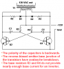
")