wireengineer
New Member
Hi guys,
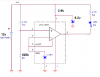
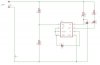
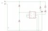
im trying to find a circuit that will monitor a 12v battery and if the voltage drops below 10v it gives a visual of sound output (LED or BUZZER).
Thanks in advance guys.
(i have found this circuit....Circuit - 9v Battery Voltage Monitor using a LTC1440 comparator - Circuits designed by David A. Johnson, P.E. but i am unsure how to alter it to meet my needs)