I recently bought four Battery Butler 12v battery long-term storage float chargers, all of them don't work afaik. They have a red 'Power' LED and a green 'Charging' LED. The red Power LEDs come on, but the green charging LEDs on all four won't come on, even on a known partially discharged 12v automotive battery. One of my older Battery Butlers still works and the red and green LEDs comes on when hooked up to the same battery. The battery voltage does not come up even a little when I hook the new BBs to it. I'm a newbie to electronics in general, but have done some reading and studying so can speak a little intelligently about it.
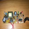
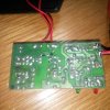
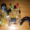
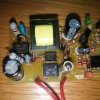
Please find attached pictures of one of the chargers. The four major ICs are: a DB107 Rectifier, an EL817 Photocoupler, a Viper12A Pulse Width Controller with high power MOSFET, and a LM358P Dual Op Amp. The rectifier is working and sends 160VDC to the 'input' side of the large 'transformer'? There are four pins soldered to the circuit board on the 'input' side, and only two pins soldered to the board on the 'output' side of the transformer. That's as far as I have been able to go with this circuit, because I don't get why 160VDC goes to a transformer. Maybe it's a choke? Not sure.
Ideally, I'm hoping someone has a schematic of the Battery Butler float charger, or can explain to me what signals I should be seeing coming in or out of what components to troubleshoot it?
Thanks for any help,
Wil