Continue to Site

Welcome to our site!

Electro Tech is an online community (with over 170,000 members) who enjoy talking about and building electronic circuits, projects and gadgets. To participate you need to register. Registration is free. Click here to register now.

  • Welcome to our site! Electro Tech is an online community (with over 170,000 members) who enjoy talking about and building electronic circuits, projects and gadgets. To participate you need to register. Registration is free. Click here to register now.

12v 6A car charger not charging?

Status
Not open for further replies.

Lykenth

New Member
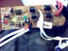
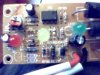
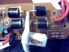
Hello, I bought a 12v 6A car charger a while back, from new, an its stopped charging. I does turn on, power LED comes on and so does the charge indicator LED too. but it dont charge my batteries. it did before so im stumped why not this time. the standing voltage on the batter will go no higher. I have done a Bulb test across the terminals and it dont come on - the charger fuse is fine. the terminals dont spark. i have took apart the charger - everything appears fine, i used a multimeter to check the current flow. it appears ok? i am learning about the inner component as i go but it does confuse me some times. the charger has a built in over charge protector.

#Summry - the charger turns on - detects the battery - but will not put power into it.

Any ideas?

IT HAS BEEN FIXED - The problem was the big white 5w resistor. so if you have a similar problem then its an area you will want to check. an its a simple part to replace =D
 

Attachments

  • Picture 001.jpg
    Picture 001.jpg
    49.8 KB · Views: 1,072
  • Picture 005.jpg
    Picture 005.jpg
    44.9 KB · Views: 964
  • Picture 011.jpg
    Picture 011.jpg
    39.6 KB · Views: 940
Last edited:
These have a voltage comparator circuit (bistable with hystersis) which works like this:

When you first connect a battery, a bistable is set. When set, the voltage limit is set to a charge voltage of ~14.2V. The charger supplies current limited by the transformer/charger (~6A) until the battery terminal voltage comes up to the higher limit. When the battery voltage exceeds the higher limit, the bistable is reset, which lowers the voltage limit to a float voltage of ~13.0V, (and turns on one of the LEDs), which is where charger holds the battery voltage as long as it remains plugged in.

What are the LEDs doing? What are the LED labeled?
 
The LEDs are not ladled. Red for charger power, yellow for charging indication, Green when fully charged.
I kind of understand what you said, i do struggle if i dont have a practical reference.
-So my charger is not reaching the upper voltage to then reset to the floating voltage?
im better at building things than the electronics running them. But from what i think i know ( very little ) is thats got something to do with the zender diodes?
Is there anything else youd like to know to possable diagnose the defective component?
 
What is the Brand and Model?

What state are the LEDs in when you first connect it to a battery? Do they ever change over time?

If you measure the battery voltage during charging, what happens?
 
Its a ; Ring Automotive Basic charge 6 ( 6A charger) Model: RCB106
When i connect the battery the yellow charge light comes on - the green one wont as it dont charge. i connected a battery to the lights to see if the work an they all do.
When i check the voltage during charging - no difference from what charge the battery original had left. When i remove the clip from the battery with the electrode on the clip, the charge gathered from the batter begins to drop. it will drop off to 1V an steady out.
 
I'd say that the fuse in the transformer, or diodes, or output transistor is blown.
 
Well i did a continuity test on the diodes, theres power coming out of the transformer, other wise the power light would not come on. so they are find. as for the out put transistor... there isant one that looks like a conventional one but there is a LM358 that when i researched what it is, has internal symbols that look like transistors to me. as its a tiny part, id imagine in expensive to replace ill change that i guess. Im happy then as my suspitions were right - that its most likly the charge regulator part =D
 
Last edited:
LM358 is a dual opamp. Likely used as a comparator. The LED on some of these chargers lights the moment the correct battery polarity is connected to the clips, even without the AC being connected.
 
i have took apart the charger - everything appears fine, i used a multimeter to check the current flow. it appears ok?
Any ideas?


So how do you know if the current is ok?

Looking at the fotos you posted, have you checked the low ohmic resistor at the bottom of the pcb near the four 6amp diodes? it could be open circuit?

These battery chargers are pretty basic ( I did have two of them at one time...) All they seem to do is charge the battery and use an op amp to determine the state of charge using window comparators...Which is what the 358 is doing...The charge current is limited by the battery's own internal resistance...Like I said, very basic..
 
Last edited:
Funny you should say that because i took it to my mates dad an hes a wiz with electronics! - he did indeed test the resistor an it was not working at all. He replaced it with another an hay presto! its working as normal =D
 
lets hop i can say the same when the inverter comes.... i wanna run under my bed thinking about ow complex its going to be haha.
 
I cant really answer that accurately, but there is a transformer that steps down the mains ( 240v 13A ) to around 15V 6A - this will reduce when charging the battery. the transformer and diodes provides the force - the circuit just manages it i guess.
 
Status
Not open for further replies.

Latest threads

New Articles From Microcontroller Tips

Back
Top