pasanlaksiri
Member
This is just another clock project. The processor that I am using here is PIC16F628A. Clock timing is very accurate thanks to RomanBlack Zero-error 1 second timer algorithm.
Link1>> Zero-error 1 second timing algorithm
Link2 >> https://www.electro-tech-online.com/threads/zezj-zero-error-zero-jitter-period-algorithm.100299/
Nothing much to say about the project so here it is")
**broken link removed** **broken link removed** **broken link removed** **broken link removed**
**broken link removed** **broken link removed** **broken link removed** **broken link removed**
**broken link removed** **broken link removed** **broken link removed** **broken link removed**
**broken link removed** **broken link removed** **broken link removed** **broken link removed**
**broken link removed**
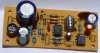
PCB Arts
**broken link removed** ***broken link removed**
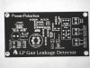
Silk Screen Layouts
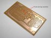
Controle Board BOTTOM
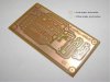
Controle_Board_TOP
SSD_Board_BOTTOM
SSD_Board_TOP
Firmware
Link1>> Zero-error 1 second timing algorithm
Link2 >> https://www.electro-tech-online.com/threads/zezj-zero-error-zero-jitter-period-algorithm.100299/
Nothing much to say about the project so here it is
**broken link removed** **broken link removed** **broken link removed** **broken link removed**
**broken link removed** **broken link removed** **broken link removed** **broken link removed**
**broken link removed** **broken link removed** **broken link removed** **broken link removed**
**broken link removed** **broken link removed** **broken link removed** **broken link removed**
**broken link removed**
PCB Arts
**broken link removed** ***broken link removed**
Silk Screen Layouts
Controle Board BOTTOM
Code:
http://www.4shared.com/file/236695715/97e5185a/Controle_Board_BOTTOM.htmlControle_Board_BOTTOM.html
Code:
http://www.4shared.com/file/236695744/9d95dc89/Controle_Board_TOP.html
Code:
http://www.4shared.com/file/236695925/b6566693/SSD_Board_BOTTOM.html
Code:
http://www.4shared.com/file/236696025/ab32f2f2/SSD_Board_TOP.htmlFirmware
Code:
http://www.4shared.com/file/236744326/a9b8c28e/GT_mini_Clock_hex.html
Last edited: