This one's baffling me.
Why can't I use GPIO3 as an input? The code below works using GPIO5 as the Serial input line.
It also works if I change to GPIO4:
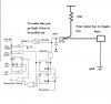
But as soon as I try GPIO3, I get continuous duplicate characters coming in - I think it's reading lows continously. I did add some code at one point to send a 1 or 0 via RS232 to tell me the level of GPIO3 and it worked fine as I alternated between Vdd and Vss. So why isn't it working from the MAX232? Why does it work on GPIO4 and 5 but not 3?
What's different about GPIO3 as an input compared to GPIO4 and GPIO5? Is there some configuration I'm missing? I've disabled MCLR (as far as I know).
Thanks,
David
Why can't I use GPIO3 as an input? The code below works using GPIO5 as the Serial input line.
It also works if I change to GPIO4:
Code:
SER_IN Equ 0x04But as soon as I try GPIO3, I get continuous duplicate characters coming in - I think it's reading lows continously. I did add some code at one point to send a 1 or 0 via RS232 to tell me the level of GPIO3 and it worked fine as I alternated between Vdd and Vss. So why isn't it working from the MAX232? Why does it work on GPIO4 and 5 but not 3?
Code:
	list p=12F675, b=8, c= 102, n=71, t=on, st=off, f=inhx32

	#include	<p12f675.inc>
	errorlevel	-302

     __CONFIG (_INTRC_OSC_NOCLKOUT & _WDT_OFF &_BODEN_OFF &_CP_OFF &_CPD_OFF & _MCLRE_OFF)

;***** FLAGS
#define 	IF_SHORT 	flags, 0
#define 	FIRST_HALF 	flags, 1
#define 	HEADER 		flags, 2
#define 	VALID 		flags, 7

;***** VARIABLE DEFINITIONS

	cblock 	0x20 			;start of general purpose registers

				Xmit_Byte        	;holds byte to xmit
            	Rcv_Byte        	;holds received byte
            	Bit_Cntr        	;bit counter for RS232
            	Delay_Count        	;delay loop counter

	endc

SER_PORT	Equ	GPIO
SER_TRIS	Equ	TRISIO
SER_IN		Equ	0x05
SER_OUT		Equ	0x04

	org	0x0000

RESET	bcf		STATUS,RP0		; Bank 0
;		clrf	STATUS			;
		clrf	GPIO			; Init GPIO
		movlw	b'00000111'		;
		movwf	CMCON			; comparator off, digital I/O

		bsf     STATUS,RP0      ; bank 1
		clrf	ANSEL			; Digital I/O

		movlw   b'00101000'     ;
        movwf   TRISIO          ; Set GPIOs (1=input/0=output)

        call    h'3FF'          ; get factory calibration value
        movwf   OSCCAL          ; set OSCCAL calibration value

        bcf     STATUS,RP0      ; bank 0                          |B0

		call	SER_INIT		; initialise serial port

; Startup beeps...

		bsf		GPIO, 0
		call delay100
		bcf		GPIO, 0
		call delay100
		bsf		GPIO, 0
		call delay100
		bcf		GPIO, 0

loop
		call	Rcv_RS232

;		movf	Rcv_Byte

		movlw	'0'
		xorwf	Rcv_Byte,0
		btfsc	STATUS, Z
		bcf		GPIO, 0

		movlw	'1'
		xorwf	Rcv_Byte,0
		btfsc	STATUS, Z
		bsf		GPIO, 0

		movlw	'2'
		xorwf	Rcv_Byte,0
		btfsc	STATUS, Z
		bcf		GPIO, 1

		movlw	'3'
		xorwf	Rcv_Byte,0
		btfsc	STATUS, Z
		bsf		GPIO, 1

		movlw	'4'
		xorwf	Rcv_Byte,0
		btfsc	STATUS, Z
		bcf		GPIO, 2

		movlw	'5'
		xorwf	Rcv_Byte,0
		btfsc	STATUS, Z
		bsf		GPIO, 2

		movlw	'6'
		xorwf	Rcv_Byte,0
		btfsc	STATUS, Z
		bcf		GPIO, 4

		movlw	'7'
		xorwf	Rcv_Byte,0
		btfsc	STATUS, Z
		bsf		GPIO, 4

		movlw	'a'
		xorwf	Rcv_Byte,0
		btfsc	STATUS, Z
		goto beep1

		movlw	'b'
		xorwf	Rcv_Byte,0
		btfsc	STATUS, Z
		goto beep2

		movlw	'c'
		xorwf	Rcv_Byte,0
		btfsc	STATUS, Z
		goto beep3

		movlw	'd'
		xorwf	Rcv_Byte,0
		btfsc	STATUS, Z
		goto beep4

		movlw	'e'
		xorwf	Rcv_Byte,0
		btfsc	STATUS, Z
		goto beep5

		movlw	'f'
		xorwf	Rcv_Byte,0
		btfsc	STATUS, Z
		goto beep6

		movlw	'g'
		xorwf	Rcv_Byte,0
		btfsc	STATUS, Z
		goto beep7

		movlw	'h'
		xorwf	Rcv_Byte,0
		btfsc	STATUS, Z
		goto beep8

		movlw	'i'
		xorwf	Rcv_Byte,0
		btfsc	STATUS, Z
		goto beep9

		goto loop

beep1	bsf		GPIO, 0
		call delay100
		bcf		GPIO, 0
		goto	loop

beep2	bsf		GPIO, 0
		call delay250
		bcf		GPIO, 0
		goto	loop

beep3	bsf		GPIO, 0
		call delay250
		call delay250
		bcf		GPIO, 0
		goto	loop

beep4	bsf		GPIO, 0
		call delay250
		call delay250
		call delay250
		bcf		GPIO, 0
		goto	loop

beep5	bsf		GPIO, 0
		call delay250
		call delay250
		call delay250
		call delay250
		bcf		GPIO, 0
		goto	loop

beep6	bsf		GPIO, 0
		call delay100
		bcf		GPIO, 0
		call delay100
		bsf		GPIO, 0
		call delay100
		bcf		GPIO, 0
		goto	loop

beep7	bsf		GPIO, 0
		call delay100
		bcf		GPIO, 0
		call delay100
		bsf		GPIO, 0
		call delay250
		call delay250
		bcf		GPIO, 0
		goto	loop

beep8	bsf		GPIO, 0
		call delay250
		call delay250
		bcf		GPIO, 0
		call delay100
		bsf		GPIO, 0
		call delay100
		bcf		GPIO, 0
		goto	loop

beep9	bsf		GPIO, 0
		call delay250
		call delay250
		bcf		GPIO, 0
		call delay100
		bsf		GPIO, 0
		call delay250
		call delay250
		bcf		GPIO, 0
		goto	loop

;-----------------------------------------------
;Serial routines

SER_INIT
            BSF     STATUS, RP0           ;select bank 1
;            BCF     SER_TRIS, SER_OUT     ;set B6 as an output
            BSF     SER_TRIS, SER_IN      ;set B7 as an input
            BCF     STATUS, RP0           ;select bank 0
;            BSF     SER_PORT, SER_OUT     ;set SER_OUT high
            RETURN

Rcv_RS232   BTFSC   SER_PORT, SER_IN      ;wait for start bit
            GOTO    Rcv_RS232
            CALL    Start_Delay	          ;do half bit time delay
            BTFSC   SER_PORT, SER_IN      ;check still in start bit
            GOTO    Rcv_RS232
            MOVLW   0x08                  ;set up to read 8 bits
            MOVWF   Bit_Cntr
            CLRF    Rcv_Byte
Next_RcvBit CALL    Bit_Delay
            BTFSS   SER_PORT, SER_IN
            BCF     STATUS    , C
            BTFSC   SER_PORT, SER_IN
            BSF     STATUS    , C
            RRF     Rcv_Byte  , f
            DECFSZ  Bit_Cntr  , f         ;test if all done
            GOTO    Next_RcvBit
            CALL    Bit_Delay
            MOVF    Rcv_Byte, W
            RETURN

Start_Delay MOVLW   0x0C
            MOVWF   Delay_Count
Start_Wait  NOP
            DECFSZ  Delay_Count , f
            GOTO    Start_Wait
            RETURN

;Bit_Delay   MOVLW   0x18   ; Original setting in code - wasn't working reliably at 9600baud
Bit_Delay   MOVLW   0x17
            MOVWF   Delay_Count
Bit_Wait    NOP
            DECFSZ  Delay_Count , f
            GOTO    Bit_Wait
            RETURN

;End of serial routines
;-----------------------------------------------

; Delay = 0.25 seconds
; Clock frequency = 4 MHz

; Actual delay = 0.25 seconds = 250000 cycles
; Error = 0 %

	cblock
	d1
	d2
	endc

			;249998 cycles
delay250
	movlw	0x4F
	movwf	d1
	movlw	0xC4
	movwf	d2
Delay_0
	decfsz	d1, f
	goto	$+2
	decfsz	d2, f
	goto	Delay_0

			;2 cycles
	goto	$+1

; Generated by http://www.piclist.com/cgi-bin/delay.exe (December 7, 2005 version)
; Sat Dec 31 06:04:07 2011 GMT

; See also various delay routines at http://www.piclist.com/techref/microchip/delays.htm
	return

; Delay = 0.1 seconds
; Clock frequency = 4 MHz

; Actual delay = 0.1 seconds = 100000 cycles
; Error = 0 %

;	cblock
;	d1
;	d2
;	endc

			;99998 cycles
delay100
	movlw	0x1F
	movwf	d1
	movlw	0x4F
	movwf	d2
Delay_1
	decfsz	d1, f
	goto	$+2
	decfsz	d2, f
	goto	Delay_1

			;2 cycles
	goto	$+1

; Generated by http://www.piclist.com/cgi-bin/delay.exe (December 7, 2005 version)
; Sat Dec 31 06:07:36 2011 GMT

; See also various delay routines at http://www.piclist.com/techref/microchip/delays.htm
	return

		end
What's different about GPIO3 as an input compared to GPIO4 and GPIO5? Is there some configuration I'm missing? I've disabled MCLR (as far as I know).
Thanks,
David