Continue to Site

Welcome to our site!

Electro Tech is an online community (with over 170,000 members) who enjoy talking about and building electronic circuits, projects and gadgets. To participate you need to register. Registration is free. Click here to register now.

  • Welcome to our site! Electro Tech is an online community (with over 170,000 members) who enjoy talking about and building electronic circuits, projects and gadgets. To participate you need to register. Registration is free. Click here to register now.

120 to 24 transformer wiring

Status
Not open for further replies.

ptm82379

New Member
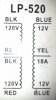
I have a transformer that I got from MPJA: https://www.mpja.com/prodinfo.asp?number=7846+TR It is a 120v to 24v center tap. I want to use each 12v on the low side seperately

It came with zero wiring diagrams. Can you help me figure out what goes where

On the high side I have 2 red, 2 blk. What are they? I assume one gets the hot lead and one gets a neutral? Or does one get a ground?

On the low side I have 2 blue and 1 yellow. I asume the 2 blue are 12 v. What is the yellow? Ground?

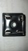
Also when the power leaves the low side the first thing it will hit is a 25A 50v bridge rectifier. It has no diagram either. Just a notch cut off of one of the corners. I would assume this to be the 50vdc positive output side and the side oppositely diagonal to be the negative. The other 2 terminals would be AC input? Do both of those terminals have to be used?

Please forgive me if these are newb questions. This is my first project.
 
I would assume the red and black are the hot and neutral connections, the blues are the two ends of the 24V winding and yellow is the centre-tap. For safety's sake it is imperative that you correctly identify which is the primary (high voltage) winding.
Do you have a multimeter with an Ohms range and a diode test function? That can be used to identify what goes where on both the transformer and rectifier.
Let us know what markings (if any) there are on the rectifier. That will aid identification of the pin-out.
Be aware that with a centre-tapped winding your two '12V' supplies won't be completely independent.
 
Last edited:
I believe what you have is the attached image. Your transformer has two primaries making it useful for 120 / 240 volt operation. For 120 volt primary you would parallel the windings tying 1&3 and 2&4 together and apply 120 volts AC. For 240 volt operation the primaries go in series and you would tie 2&3 together and apply 240 volts AC to 1&4.

The secondary should be as drawn. If you plan to use this you should understand it and be careful working around mains power.

The attached is just an example! It shows how a transformer like yours is likely configured.

Ron
 

Attachments

  • Trans PinOut.gif
    Trans PinOut.gif
    4.3 KB · Views: 3,011
Last edited:
Found a tiny sticker

Reloadron, I looked in the box and there was a sticker on one that fell off. I almost threw it away when I looked it was very similar to what you posted. It doesnt say anything about 240 though...

I want 120 in on high side and 2- 12vac outs...Where does the center tap go?
What connects to the blacks and reds. If you look at the windings each red and black are paired together.

Check out the attachment
 

Attachments

  • transformer.jpg
    transformer.jpg
    626.1 KB · Views: 1,095
It is obvious that when the two 120V BLK and RED windings are in series then they are 240V.
It is also obvious that 12V is available from one BLUE and the YEL wires and another 12V is available from the other BLUE and the YEL wires.

Why did you buy foreign parts without any datasheets? Are they certified? Will they cause your house to burn down?
 
Reloadron, I looked in the box and there was a sticker on one that fell off. I almost threw it away when I looked it was very similar to what you posted. It doesnt say anything about 240 though...

I want 120 in on high side and 2- 12vac outs...Where does the center tap go?
What connects to the blacks and reds. If you look at the windings each red and black are paired together.

Check out the attachment

OK, seeing that my little drawing was off base. Each primary winding is a Black / Red. So if you want to run off 120 VAC you would pair the two black and the two red. This effectively places the two primaries in parallel which is what you want for 120 VAC on the primary side. I believe 120 volts is what you are after correct?

I edited my image previously posted.

Ron
 
Last edited:
Thanks Ron...yes 120 is what im after...
Now what to do with the yellow wire...the 2 blue are 12vac but the yellow center tap just says 10a...
By the way thank you for being understanding with me...its not so obvious when its your first project...

Where would my blues and yellows terminate on my rectifier. It is 25a 50v 4 terminal bridge rectifier from radio shack. There will be one on each 12vac out feom the transformer...

Again thank you for your help Ron.
 
OK, the transformer has a 24 volt secondary. That is 24 volts between the two blue wires of the secondary. However, the secondary also has a CT (Center Tap) so between either Blue wire and the Yellow (CT) you will measure 12 volts. Thus the center tap is common ) volts to either of the blue wires. Now what exactly are you trying to do here? I gather you want two 12 volt outputs?

Ron
 
Where would my blues and yellows terminate on my rectifier. It is 25a 50v 4 terminal bridge rectifier from radio shack.

There will be one on each 12vac out feom the transformer...

Sorry, but that will probably not work.

It all depends on what you want to do with the outputs of the two rectifiers.
There is great scope for a lot of smoke here, what you really need is a transformer with two completely separate 12v secondary windings.

JimB
 
Maybe he is making a power supply that has a positive output voltage, a negative output voltage and a common 0V.
 
Two separate secondary windings, as JimB states, would have been preferable.
It is possible to use your centre tapped winding and the bridge rectifier to generate a positive DC voltage supply and a negative DC voltage supply, sharing a common ground connection. Note that they won't be fully independent, because of the shared connection.
I suggest you read up about methods of rectifying AC voltages before you venture further with this project.

Edit: You pipped me at the post, AG!
 
Last edited:
This is what everyone is getting at. Note the attached image. If you want a split +12 and -12 volt supply you can do it. However, if you want two 12 volt supplies, independent of each other you have a problem.

The attached shows what you have setup as a split +/- 12 volt supply and what you would need for a independent 12 volt setup. Note the drawings are crude not showing filter capacitors but you should get the idea. So it comes down to what you actually want.

Ron
 

Attachments

  • 12 volt supplies.gif
    12 volt supplies.gif
    22.7 KB · Views: 1,181
You can't get two separate (isolated) 12V outputs from a center-tapped 24V winding so the best you can do is use the output in a two-diode full-wave rectifier configuration to get one 12V output as shown here.
 
OK, the transformer has a 24 volt secondary. That is 24 volts between the two blue wires of the secondary. However, the secondary also has a CT (Center Tap) so between either Blue wire and the Yellow (CT) you will measure 12 volts. Thus the center tap is common ) volts to either of the blue wires. Now what exactly are you trying to do here? I gather you want two 12 volt outputs?

Ron

I want 2 -12vac outs from the Transformer going into this full wave bridge rectifier (attached) then dc goes into my circuit board.

I guess what I need to know is what goes to the red high side, what goes to the black high side, and where do the yellow and blues connect on the rectifiers.
 

Attachments

  • 2011-09-25_12-47-12_610.jpg
    2011-09-25_12-47-12_610.jpg
    858.8 KB · Views: 347
Last edited:
You can't get two separate (isolated) 12V outputs from a center-tapped 24V winding so the best you can do is use the output in a two-diode full-wave rectifier configuration to get one 12V output as shown here.

They dont have to be isolated. I just want 2- 12vac outs...
 
I just want 2- 12vac outs
Then you don't need a rectifier. Yellow is the common '0V' and each blue is +-12VAC with respect to 0V.
You did mean AC, didn't you??
 
No each circuit needs at least +12vdc to operate. I am driving ignition coils. I will have to rectify the voltage to dc
 
Why can't two or more ignition coils be powered from a single supply (using full-wave rectification as Crutschow suggested above) ?
 
Status
Not open for further replies.

New Articles From Microcontroller Tips

Back
Top