Continue to Site

Welcome to our site!

Electro Tech is an online community (with over 170,000 members) who enjoy talking about and building electronic circuits, projects and gadgets. To participate you need to register. Registration is free. Click here to register now.

  • Welcome to our site! Electro Tech is an online community (with over 170,000 members) who enjoy talking about and building electronic circuits, projects and gadgets. To participate you need to register. Registration is free. Click here to register now.

12 Hour Digital Clock Project Help

Status
Not open for further replies.

macdaddy97

New Member
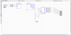
I would like some guidance on how to properly connect my clock circuit to a 7 segment display. I do not have to display the seconds. The way I have shown registers on the board on the correct display, but it only displays the middle light on the display. I've looked everywhere for a similar set up to follow but have had no luck. Please help.
 

Attachments

  • Capture67.PNG
    Capture67.PNG
    42.7 KB · Views: 240
For a simple non-multiplexed display, you would need a 7448 for each digit, linked to the appropriate outputs of the counters and feeding a 7 segment LED. You would also need enough pins to directly connect every segment.

It's usually more practical to use a multiplexed output.

For that, you need a separate counter to step through each wanted output digit and decode that to give a single "digit" output for each 7 segment digit, and at the same time feed the appropriate counter digit through the 7 segment decoder and output the data from that on the segment drive pins.

This shows the basic principle and possible electrical connections:

The segment decoder output is "time shared" between the overall characters of the display, with the segment data and common power connection to each digit being rapidly changed so all digits are shown at a refresh rate of at least 50 times a second to avoid any visible flickering.

The majority of multi-digit LED displays work like this as it saves a lot of components, for a little extra software.

Using TTL IC emulation you need a binary counter (eg. 7493) clocked at eg. 200 to 400Hz, a digit decoder (eg. 74138 or 139), and a multiplexer/data selector to select the digit data sent to the 7 segment decoder at each count, eg. a couple of 74153s.
 
Status
Not open for further replies.

Latest threads

New Articles From Microcontroller Tips

Back
Top