Electro Tech is an online community (with over 170,000 members) who enjoy talking about and building electronic circuits, projects and gadgets. To participate you need to register. Registration is free. Click here to register now.
Welcome to our site! Electro Tech is an online community (with over 170,000 members) who enjoy talking about and building electronic circuits, projects and gadgets. To participate you need to register. Registration is free. Click here to register now.
Hi. Can anyone out there help me by providing a circuit schematic for converting 10 VAC to 3 VDC? It needs very little current at the 3 VDC side, maybe 10ma at most. Any help would be great -thank you.
Thanks for the reply. Any idea of the exact values of the caps to filter the signal? Also, any schematic would be great - I can't seem to find any specific values for these components on the internet.
Thanks for the reply. Any idea of the exact values of the caps to filter the signal? Also, any schematic would be great - I can't seem to find any specific values for these components on the internet.
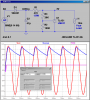
Here is how I would do it. I'm assuming that one end of your 10Vac source can be common to the minus side of your load. I'm also assuming that it is 10Vrms, or about 28Vp-p. If not, write back and I can adjust the schematic. You can diddle R3 from zero to ~ 100K, which will adjust the output voltage from 2.5V to ~5V.
Thanks mike and others...that circuit should work fine. I am trying to connect 4 (four) small flickering type LED candles to a landscape light transformer. There are other lights on the landscape transformer, so the voltage at my attachment point is only 10 VAC. The four LED candles were originally made to run on a CR2032 3V battery each. Should I connect the LED candles in parallel to the above circuit?
Thanks mike and others...that circuit should work fine. I am trying to connect 4 (four) small flickering type LED candles to a landscape light transformer. There are other lights on the landscape transformer, so the voltage at my attachment point is only 10 VAC. The four LED candles were originally made to run on a CR2032 3V battery each. Should I connect the LED candles in parallel to the above circuit?
Hook your load where it says "Your Load" in the schematic. The component I1 is just what I used to load the circuit for the simulation.
Where you using a Multimeter for reading the 10Vac? If so, most meters read effective AC (called root mean square, or RMS), so the 28V peak-to-peak I used in the simulation is equivalent to the 10Vrms you would read with your multimeter.
This site uses cookies to help personalise content, tailor your experience and to keep you logged in if you register.
By continuing to use this site, you are consenting to our use of cookies.