Hi all, I'm new to this forum, so pleased to meet you
I was wondering if you could help me with my project, here is the background. I’m building a solar cell system, and I would like to install some permanent Volt and ampers meters to monitor constantly the voltage and ampers that come out from the cells. I’m going to do several of these so I would like to keep it cheap.
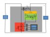
I draw a general diagram to show you the idea. I have basic knowledge of electronics, so I at least know that V=IR and W=VA. So I saw on other blogs how to build a voltmeter with a PIC microprocessor and a LCD display, but I would like to add the functionality of an ammeter also.
So In the diagram attached, the blue box represent the PIC and LCD system, this system requires a 0 to 5 volts only input to be measured, so for example if my solar cells throw from 0 to 20 volts I always have to convert it to 0 to 5 volts, that’s why the divider. And I think it is wired in parallel with the solar cells.
Now to measure the current I read that I have to put the ammeter in series and that I needed a shunt resistor and that the ammeter must have the lowest possible resistance. My solar cells throw from 0 to 10 amps. So I placed a 0.1 ohms resistance (1 watt) trying to keep things simple. Then I suppose I have to measure the voltage on that resistance and I figure that it should read from 0 to 1 volt. Now I have to amplify that voltage and convert it to a range of 0 to 5 to be able to feed it to the PIC system correct?
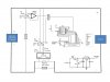
Believing that I’m correct so far, I saw on site that I could use and operational amplifier to increase that voltage, and so the basic diagrams. I tried to figure out the basic theory with op-amps but got more confused with the issues about offsets, gains in Mhz or db, and cascade connections. So does anybody know a simple way to amplify the voltage?
I was thinking on using switches to divert the current and make it a parallel circuit or serial.
So can anybody comment on my project? Are the resistance values all wrong? For example, I also read that the voltmeter should have big impedance so are the resistance values more or less fine?
The five volts needed to feed everything will come from another source and I read that it has to be regulated so I have the closest to 5v all the time.
thanks to anyone in advance
I was wondering if you could help me with my project, here is the background. I’m building a solar cell system, and I would like to install some permanent Volt and ampers meters to monitor constantly the voltage and ampers that come out from the cells. I’m going to do several of these so I would like to keep it cheap.
I draw a general diagram to show you the idea. I have basic knowledge of electronics, so I at least know that V=IR and W=VA. So I saw on other blogs how to build a voltmeter with a PIC microprocessor and a LCD display, but I would like to add the functionality of an ammeter also.
So In the diagram attached, the blue box represent the PIC and LCD system, this system requires a 0 to 5 volts only input to be measured, so for example if my solar cells throw from 0 to 20 volts I always have to convert it to 0 to 5 volts, that’s why the divider. And I think it is wired in parallel with the solar cells.
Now to measure the current I read that I have to put the ammeter in series and that I needed a shunt resistor and that the ammeter must have the lowest possible resistance. My solar cells throw from 0 to 10 amps. So I placed a 0.1 ohms resistance (1 watt) trying to keep things simple. Then I suppose I have to measure the voltage on that resistance and I figure that it should read from 0 to 1 volt. Now I have to amplify that voltage and convert it to a range of 0 to 5 to be able to feed it to the PIC system correct?
Believing that I’m correct so far, I saw on site that I could use and operational amplifier to increase that voltage, and so the basic diagrams. I tried to figure out the basic theory with op-amps but got more confused with the issues about offsets, gains in Mhz or db, and cascade connections. So does anybody know a simple way to amplify the voltage?
I was thinking on using switches to divert the current and make it a parallel circuit or serial.
So can anybody comment on my project? Are the resistance values all wrong? For example, I also read that the voltmeter should have big impedance so are the resistance values more or less fine?
The five volts needed to feed everything will come from another source and I read that it has to be regulated so I have the closest to 5v all the time.
thanks to anyone in advance