Hello and welcome. Feel free to skip any sections you don't want to read. To make this circuit work you really only need the schematic picture and some of the text after it. The "over explaining" is for new people who want to fully understand what is going on here, and are willing to take the time to learn. If you are an EE type already, and feel that I have made an error somewhere, PM me with the details. (I *DON'T* care about correct spelling and grammar, {or idioms... apparently} like... ever)
Overview
When you hook a 12v box fan directly up to 12v, as you would expect it runs full blast, maximum air flow. This is great for "the best cooling", but it turns out this not actually optimum cooling. Contrary to what you most likely have heard, most things electronic DO NOT go faster or better if they are any cooler that normal operating temperature. What we are really after when we cool these things is TO REMOVE HEAT BEING MADE!!! And this has little to do with the absolute temperature in reality. Most times what you really want is just the bare minimum cooling you can get away with. Otherwise you are making excessive noise, collecting extra dust, and putting more wear on your fans bearings, all for very little gain. So... How do we do this properly?

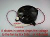
First thought, you could just drop the power to the fan with something like a resistor. Or a bunch of diodes in series with the fan, like in the above picture. Or a transistor and a knob. This would certainly make it run slower. But what happens if you accidentally go to slow for to long? What if you set it up just right, but the device starts to make more heat suddenly? (CPU's do this ALL the time). Wouldn't it be nice if the fan could some how "sense" when the device it's cooling was getting hot? Then it could crank up the air flow and give it better cooling when needed. This is where the idea of temperature controlled fan speed comes in. And there are as many ways to do it as there are stars in the sky.

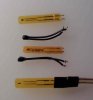
The heart of any temperature controlled circuit is... the temperature sensor of course. Pictured above is a few samples of what is known as a "Negative Temperature Coefficient resistance temperature detector" or "NTC thermistor" for short. Most NTC thermistor have a resistance value that is given for a standard point that's around room temperature or 21c. (ours should be 10K at 21c) Unlike most normal resistive substances, an NTC thermistor *REDUCES* it's resistance when it gets hot. And does so by quite a large percentage I might add. Now we can take advantage of this change in resistance to create a voltage divider that will output a varying voltage in response to a changing temperature. If the NTC thermistor is on the more positive side of the divider, then the output voltage should swing higher as temps go up, and lower as they go down.
At this point, it would seem that all we need to do is attach the output of this voltage divider to the positive lead of our box fan and we are done, simple as that. Well Sadly... things are not quite that simple. Turns out that although the voltage changes a lot, it's not enough by it's self. And MORE importantly, there is not enough current to even really light an LED properly... let alone power a decent box fan. So... how do we fix this problem? This is where some amplification comes in handy.

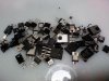
Pictured above is a wide assortment of "N-channel enhancement mode Metal Oxide Semiconductor Field Effect Transistors", or "N-channel MOSFET's" for short. MOSFET's are a type of device that will change it's resistance when a voltage is given to it. They are black square-ish devices with three pins and a tab of some kind, usually metal as seen above. The difference between an N-channel MOSFET and an NTC thermistor is that the MOSFET can change it's resistance faster/farther for a given input, *AND* it can handle much much more power going through it without melting. Well, this looks like EXACTLY what we need for fixing the two problems with the NTC thermistor. So... now it sounds like it's time to build a circuit.
The Circuit
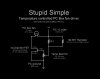
This circuit is something that I designed way back when I was a kid. (yes, previous child prodigy here). And as far as I know, I am the originator of this particular method for box fan control. Though it certainly would not surprise me if it turned out this is old news as it's a fairly obvious circuit configuration. In any case, what you see here is all my original work to be sure. And all though it is a bit picky at times, requiring a wall of text to explain how to get the most out of it. To this date I have been unable to out do this circuit for simplicity and effectiveness in doing what it does.

Getting parts
First off. NOTHING is sacred here parts wise. You can substitute, chop, cut, paste, move, slice and dice and redesign this whole thing just about anyway you want. This is why there are no part numbers. This makes it easy to work with just what ever you have laying around. However, exactly how good it preforms is up to your choices and proper fine tuning. I personally prefer to salvage as many parts as I can. And this circuit is designed with that in mind. The only parts that could be considered "uncommon" in this circuit (If you choose to get the best parts possible that is) is the NTC thermistor and Multiturn pots.
You can get NTC thermistors easily enough out of almost any "smart battery pack". Battery's such as a laptop or cell phone battery are good candidates. If it's a plastic box that says Li-ion or Li-Po, chances are it has a protection circuit with at least one NTC thermistor in it somewhere. They will be right on a cell and be either the bead type, or a flat orange film type. Other circuits that need to safely shut down when they get hot may also have some. The important thing to know is what they look like and how they behave. I recommend a Google images search before you go hunting for NTC's. For this circuit you want a 10K ohm value. Which is lucky (planed actually) as almost all of them you can salvage are this value. That being said, I have seen them in all shapes and sizes so get measurements before you build. THE ONES USED AS SERGE SUPPRESSORS IN SMPS'S ARE GENERALLY NOT SUITABLE FOR THIS CIRCUIT.

As for The MOSFET. There are SO MANY sources of suitable MOSFET's that you really have no excuse for not finding one in salvage. Most older computer motherboards have at least one high power/low voltage unit soldered down near the CPU socket. Another acceptable source is the power switch in *ANY* electronic devices power supply. To know if you hit pay dirt, check part numbers on Google. Use "nubers-on-the-top-of-the-black-thing + datasheet", just like this "IRF630 datasheet". It should jump right out in your face that you have a MOSFET and not something else with this method. Though you may have to play "connect the links" to get to the actual datasheet. When you do, save the datasheet to your computer, or at least get the pinout. With all the pins pointing towards you most every MOSFET's pinouts is arranged so that, the left is the "Gate", the middle (and the tab) is "Drain", and right is "Source". Of course, There are very easy ways to identify that you actually have a MOSFET and not something else with out the datasheet. Simply by virtue of testing it.
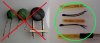
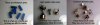
The potentiometer (refereed to in the schematic as "temp set pot") can be almost any variable resistance you can get your hands on. It should have a value of around 15k ohms, but you can go as high as 30K and as low as 5k. THE BEST AND MOST HIGHLY RECOMMENDED *TYPE* would be a "Multiturn" trimmer, as they are more forgiving to finer adjustments and this will make setting the base temp much smoother. Keep in mind that multiturn trimmers are also much harder to find in salvage. Second to a multiturn trimmer would be your normal high quality volume pot. Keep and use the knob and nut also if you can, as they make adjusting MUCH smoother. NON-logarithmic pots are best of the audio pots, but you can make use of both. If you can't find either of those types, you can still try and use a normal trimmer pot. These are very common in CRT TV's and VCR's. They usually have a slot on the top and require a screw driver to tune. They are not a very good choice as they are very sensitive, even with a steady hand. Lastly, if you ABSOLUTELY must... you *CAN* use normal resistors in a voltage divider configuration. Though you will be pulling your hair out while doing this. Remember that you can always parallel and series your resistors to create different "virtual resistors" if need be. Though at this level of butchering the circuit, I would just assume live with full power fan's myself. You will *NOT* have fun using normal resistors for the trimmer pot, been there, done that. Take my advice and don't even try. Even standard trimmer pots suck honestly. Good news is that if you manage to get just the right values, it will be hard to change the setting by accident.

The fixed resistor "R1" is an adjustment and is "to-be-determined" upon circuit assembly. It's mostly dictated by the values of the above parts and how sensitive the NTC thermistor is. R1 is used to adjust the sensitivity of the NTC, lower values being less sensitive, higher being more. In some cases it's not even needed. But it is usually over sensitive so it will normally be 4.7k (4k7 or yellow, purple, red, gold) or 10k (Brown, black, orange, gold). Keep a lot of different values around to try out, as this is one main way to tune this circuit. There really is no better way to choose R1 than to just try different values till one works well for you. Mostly it should match the pot's max value. If your NTC thermistor is anything other than 10K at 21c... every thing changes.
For a circuit board. Well... It's 5 low pin count parts *INCLUDING* the fan, so I just birds nest it all together usually. Though, I have also tried just about every electronic insulator known to man as a board. Nails in a piece of wood, Cereal box, perforated cardboard, old pcb with the traces taken off, book cover, thin piece of wood, plastic sides of liquid containers, Whatever works... doesn't matter... none of this matters.
AND ALL OF THE PARTS CAN BE BOUGHT FOR LESS THAN $10.00 IF YOUR SMART AND SHOP AROUND. Start with the usual suspects, DigiKey, Mouser, Ebay.
You should now have plenty of parts to play with.
Building and tuning the circuit
First thing you need to know... You should avoid powering this circuit up without the NTC thermistor attached to some kind of mass. NTC thermistors tend to self heat, which leads to lower resistance and thus MORE self heating, finally ending in self destruction and tears. To also help avoid this problem, make sure you have the "temp set pot" adjusted in the middle of it's range before installing, and turn it *SLOWLY* when tuning the circuit. I have lost plenty of NTC thermistors to this problem. (yes, the circuit could be made to fix things, and no I don't care. If you do it right you won't have this problem either way)
Second, every MOSFET and NTC thermistor is a little different. And this circuit is sensitive at times. Because of this, exactly what part values you will need to use will vary widely. I suggest you get an assortment of parts and trial and error the circuit together. If you build this thing and find that it doesn't work exactly as you would like, start by changing the MOSFET. You may want to try and change the NTC thermistor also, but I suggest just trying to tune it better with R1. You should tune the circuit with the "temp set pot" and R1 after each and every parts swapping or change. I have had all sorts of problems magically go away after switching things out for other parts then retuning it. (High voltage MOSFET's tend to dislike this circuit more than low voltage ones do)
Third, I recommend when your fleshing out this circuit, use a simple cheep 12v ~500mA wall adapter as your power supply. Or you can hook together 8 "over the counter battery's" or 10 Ni-Cd's in series. DON'T use Li-ion cells AT ALL because a short circuit will easily cause a fire or explosion. And I don't recommend using your PC power supply either as it could easily destroy the circuit and the supply.
Finally, If your fan is exceptionally large, you may want to consider putting a heat sink on the MOSFET. You *CAN* just bolt it to your case *IF* it's in a FULLY plastic package. But if the tab is metal, you MUST insulate it from the case. If the tab comes in contact with your computer case, that will basically ground the fan out and the circuit will act like the sensor is fully hot. It could even ruin your computer, power supply, and circuit instantly under certain circumstances. So be extra careful here. in retrospect, I have never needed a heat sink even once.
Well.... That should about do it. If you read all the way to the end of this "epic novel", then congrats! This was probably the longest explanation given to such a simple circuit in all of history. And if you have any problems... Tough luck I have given you more than enough to work with right here. I guess you can always try the forums. But You shouldn't need that. It's a simple circuit. Just try it and see for yourself.
Happy circuit building.
-()blivion
Overview
When you hook a 12v box fan directly up to 12v, as you would expect it runs full blast, maximum air flow. This is great for "the best cooling", but it turns out this not actually optimum cooling. Contrary to what you most likely have heard, most things electronic DO NOT go faster or better if they are any cooler that normal operating temperature. What we are really after when we cool these things is TO REMOVE HEAT BEING MADE!!! And this has little to do with the absolute temperature in reality. Most times what you really want is just the bare minimum cooling you can get away with. Otherwise you are making excessive noise, collecting extra dust, and putting more wear on your fans bearings, all for very little gain. So... How do we do this properly?
First thought, you could just drop the power to the fan with something like a resistor. Or a bunch of diodes in series with the fan, like in the above picture. Or a transistor and a knob. This would certainly make it run slower. But what happens if you accidentally go to slow for to long? What if you set it up just right, but the device starts to make more heat suddenly? (CPU's do this ALL the time). Wouldn't it be nice if the fan could some how "sense" when the device it's cooling was getting hot? Then it could crank up the air flow and give it better cooling when needed. This is where the idea of temperature controlled fan speed comes in. And there are as many ways to do it as there are stars in the sky.
The heart of any temperature controlled circuit is... the temperature sensor of course. Pictured above is a few samples of what is known as a "Negative Temperature Coefficient resistance temperature detector" or "NTC thermistor" for short. Most NTC thermistor have a resistance value that is given for a standard point that's around room temperature or 21c. (ours should be 10K at 21c) Unlike most normal resistive substances, an NTC thermistor *REDUCES* it's resistance when it gets hot. And does so by quite a large percentage I might add. Now we can take advantage of this change in resistance to create a voltage divider that will output a varying voltage in response to a changing temperature. If the NTC thermistor is on the more positive side of the divider, then the output voltage should swing higher as temps go up, and lower as they go down.
At this point, it would seem that all we need to do is attach the output of this voltage divider to the positive lead of our box fan and we are done, simple as that. Well Sadly... things are not quite that simple. Turns out that although the voltage changes a lot, it's not enough by it's self. And MORE importantly, there is not enough current to even really light an LED properly... let alone power a decent box fan. So... how do we fix this problem? This is where some amplification comes in handy.
Pictured above is a wide assortment of "N-channel enhancement mode Metal Oxide Semiconductor Field Effect Transistors", or "N-channel MOSFET's" for short. MOSFET's are a type of device that will change it's resistance when a voltage is given to it. They are black square-ish devices with three pins and a tab of some kind, usually metal as seen above. The difference between an N-channel MOSFET and an NTC thermistor is that the MOSFET can change it's resistance faster/farther for a given input, *AND* it can handle much much more power going through it without melting. Well, this looks like EXACTLY what we need for fixing the two problems with the NTC thermistor. So... now it sounds like it's time to build a circuit.
The Circuit
This circuit is something that I designed way back when I was a kid. (yes, previous child prodigy here). And as far as I know, I am the originator of this particular method for box fan control. Though it certainly would not surprise me if it turned out this is old news as it's a fairly obvious circuit configuration. In any case, what you see here is all my original work to be sure. And all though it is a bit picky at times, requiring a wall of text to explain how to get the most out of it. To this date I have been unable to out do this circuit for simplicity and effectiveness in doing what it does.
Getting parts
First off. NOTHING is sacred here parts wise. You can substitute, chop, cut, paste, move, slice and dice and redesign this whole thing just about anyway you want. This is why there are no part numbers. This makes it easy to work with just what ever you have laying around. However, exactly how good it preforms is up to your choices and proper fine tuning. I personally prefer to salvage as many parts as I can. And this circuit is designed with that in mind. The only parts that could be considered "uncommon" in this circuit (If you choose to get the best parts possible that is) is the NTC thermistor and Multiturn pots.
You can get NTC thermistors easily enough out of almost any "smart battery pack". Battery's such as a laptop or cell phone battery are good candidates. If it's a plastic box that says Li-ion or Li-Po, chances are it has a protection circuit with at least one NTC thermistor in it somewhere. They will be right on a cell and be either the bead type, or a flat orange film type. Other circuits that need to safely shut down when they get hot may also have some. The important thing to know is what they look like and how they behave. I recommend a Google images search before you go hunting for NTC's. For this circuit you want a 10K ohm value. Which is lucky (planed actually) as almost all of them you can salvage are this value. That being said, I have seen them in all shapes and sizes so get measurements before you build. THE ONES USED AS SERGE SUPPRESSORS IN SMPS'S ARE GENERALLY NOT SUITABLE FOR THIS CIRCUIT.
As for The MOSFET. There are SO MANY sources of suitable MOSFET's that you really have no excuse for not finding one in salvage. Most older computer motherboards have at least one high power/low voltage unit soldered down near the CPU socket. Another acceptable source is the power switch in *ANY* electronic devices power supply. To know if you hit pay dirt, check part numbers on Google. Use "nubers-on-the-top-of-the-black-thing + datasheet", just like this "IRF630 datasheet". It should jump right out in your face that you have a MOSFET and not something else with this method. Though you may have to play "connect the links" to get to the actual datasheet. When you do, save the datasheet to your computer, or at least get the pinout. With all the pins pointing towards you most every MOSFET's pinouts is arranged so that, the left is the "Gate", the middle (and the tab) is "Drain", and right is "Source". Of course, There are very easy ways to identify that you actually have a MOSFET and not something else with out the datasheet. Simply by virtue of testing it.
The potentiometer (refereed to in the schematic as "temp set pot") can be almost any variable resistance you can get your hands on. It should have a value of around 15k ohms, but you can go as high as 30K and as low as 5k. THE BEST AND MOST HIGHLY RECOMMENDED *TYPE* would be a "Multiturn" trimmer, as they are more forgiving to finer adjustments and this will make setting the base temp much smoother. Keep in mind that multiturn trimmers are also much harder to find in salvage. Second to a multiturn trimmer would be your normal high quality volume pot. Keep and use the knob and nut also if you can, as they make adjusting MUCH smoother. NON-logarithmic pots are best of the audio pots, but you can make use of both. If you can't find either of those types, you can still try and use a normal trimmer pot. These are very common in CRT TV's and VCR's. They usually have a slot on the top and require a screw driver to tune. They are not a very good choice as they are very sensitive, even with a steady hand. Lastly, if you ABSOLUTELY must... you *CAN* use normal resistors in a voltage divider configuration. Though you will be pulling your hair out while doing this. Remember that you can always parallel and series your resistors to create different "virtual resistors" if need be. Though at this level of butchering the circuit, I would just assume live with full power fan's myself. You will *NOT* have fun using normal resistors for the trimmer pot, been there, done that. Take my advice and don't even try. Even standard trimmer pots suck honestly. Good news is that if you manage to get just the right values, it will be hard to change the setting by accident.
The fixed resistor "R1" is an adjustment and is "to-be-determined" upon circuit assembly. It's mostly dictated by the values of the above parts and how sensitive the NTC thermistor is. R1 is used to adjust the sensitivity of the NTC, lower values being less sensitive, higher being more. In some cases it's not even needed. But it is usually over sensitive so it will normally be 4.7k (4k7 or yellow, purple, red, gold) or 10k (Brown, black, orange, gold). Keep a lot of different values around to try out, as this is one main way to tune this circuit. There really is no better way to choose R1 than to just try different values till one works well for you. Mostly it should match the pot's max value. If your NTC thermistor is anything other than 10K at 21c... every thing changes.
For a circuit board. Well... It's 5 low pin count parts *INCLUDING* the fan, so I just birds nest it all together usually. Though, I have also tried just about every electronic insulator known to man as a board. Nails in a piece of wood, Cereal box, perforated cardboard, old pcb with the traces taken off, book cover, thin piece of wood, plastic sides of liquid containers, Whatever works... doesn't matter... none of this matters.
AND ALL OF THE PARTS CAN BE BOUGHT FOR LESS THAN $10.00 IF YOUR SMART AND SHOP AROUND. Start with the usual suspects, DigiKey, Mouser, Ebay.
You should now have plenty of parts to play with.
Building and tuning the circuit
First thing you need to know... You should avoid powering this circuit up without the NTC thermistor attached to some kind of mass. NTC thermistors tend to self heat, which leads to lower resistance and thus MORE self heating, finally ending in self destruction and tears. To also help avoid this problem, make sure you have the "temp set pot" adjusted in the middle of it's range before installing, and turn it *SLOWLY* when tuning the circuit. I have lost plenty of NTC thermistors to this problem. (yes, the circuit could be made to fix things, and no I don't care. If you do it right you won't have this problem either way)
Second, every MOSFET and NTC thermistor is a little different. And this circuit is sensitive at times. Because of this, exactly what part values you will need to use will vary widely. I suggest you get an assortment of parts and trial and error the circuit together. If you build this thing and find that it doesn't work exactly as you would like, start by changing the MOSFET. You may want to try and change the NTC thermistor also, but I suggest just trying to tune it better with R1. You should tune the circuit with the "temp set pot" and R1 after each and every parts swapping or change. I have had all sorts of problems magically go away after switching things out for other parts then retuning it. (High voltage MOSFET's tend to dislike this circuit more than low voltage ones do)
Third, I recommend when your fleshing out this circuit, use a simple cheep 12v ~500mA wall adapter as your power supply. Or you can hook together 8 "over the counter battery's" or 10 Ni-Cd's in series. DON'T use Li-ion cells AT ALL because a short circuit will easily cause a fire or explosion. And I don't recommend using your PC power supply either as it could easily destroy the circuit and the supply.
Finally, If your fan is exceptionally large, you may want to consider putting a heat sink on the MOSFET. You *CAN* just bolt it to your case *IF* it's in a FULLY plastic package. But if the tab is metal, you MUST insulate it from the case. If the tab comes in contact with your computer case, that will basically ground the fan out and the circuit will act like the sensor is fully hot. It could even ruin your computer, power supply, and circuit instantly under certain circumstances. So be extra careful here. in retrospect, I have never needed a heat sink even once.
Well.... That should about do it. If you read all the way to the end of this "epic novel", then congrats! This was probably the longest explanation given to such a simple circuit in all of history. And if you have any problems... Tough luck
I have given you more than enough to work with right here. I guess you can always try the forums. But You shouldn't need that. It's a simple circuit. Just try it and see for yourself.Happy circuit building.
-()blivion
-
 Diods_and_Fan.jpg
 -
 Thermistors.jpg
 -
 Bunch of FETs.jpg
 -
 NO-OK.jpg
 -
 Temp-controlled Fan driver.jpg
 -
 Pot line up.jpg
