Continue to Site

Welcome to our site!

Electro Tech is an online community (with over 170,000 members) who enjoy talking about and building electronic circuits, projects and gadgets. To participate you need to register. Registration is free. Click here to register now.

  • Welcome to our site! Electro Tech is an online community (with over 170,000 members) who enjoy talking about and building electronic circuits, projects and gadgets. To participate you need to register. Registration is free. Click here to register now.

A easy 3 dollar broad for the 18f1220

Status
Not open for further replies.

be80be

Well-Known Member
A easy 3 dollar board for the 18f1220

Here how I made it though it would be good to share it with nub's like my self. Here a fast how you do it.
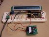
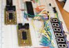
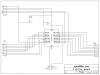
A cheap 3 dollar board for the 18f1220 And a pickit2
Get you a grid style pc board radio shack 276-150 will do 25 pin header strip 1 10kohm resistor
1 1N4148 diode and about 1foot 4 wire phone solid copper. 1 18 pin pdip socket.
Cut you two 8 pin headers one 5 pin header and 1 four pin header and place on board like in my drawing when you get done you will be able to use all the ports to play with have fun
Here the circuit
And here some pic**broken link removed**
**broken link removed** hope some one will get something out of it.
 

Attachments

  • 18f1220c.PNG
    18f1220c.PNG
    9.7 KB · Views: 336
Last edited:
Where do you get those small veroboards with the holes cut and tracks suitable for ICs in the middle? I can't seem to find them in the UK, only normal stripboard.
 
lol thats from Radio Shack. They sell both those

Cheers AtomSoft. In the UK we seem to have very overpriced stores with not much stock (e.g. Maplin) or trade suppliers who list every component under the sun, sometimes with a 2 week lead time (RS or Farnell).

I ordered from Futurelec last night after seeing it in your signature, will have to see how many weeks it takes!

And thanks to the original poster, I'm about to make something similar so this is a good start.
 
Cheers AtomSoft. In the UK we seem to have very overpriced stores with not much stock (e.g. Maplin) or trade suppliers who list every component under the sun, sometimes with a 2 week lead time (RS or Farnell).

Two week lead time? - what are you ordering?.

RS and Farnell have incredibly fast deliveries, if it's not there next day I would be absolutely amazed - even ordering Saturday delivery is usually Monday.
 
Two week lead time? - what are you ordering?

My point was more that they are designed as trade suppliers and hence stock every device in every package (e.g. SMD). This is quite daunting if you're inexperienced.

It's a little bit different to a "hobbyist" website which will just sell transistor X in the most sensible package for DIY use. And I did only have to wait 2 weeks once (for cables I think) so that was a little unfair!

I don't want to jump on the original thread but if you do know of a UK supplier of the small boards that people on here seem to use, that would be handy :)
 
That's funny
Where do you get those small veroboards with the holes cut and tracks suitable for ICs in the middle? I can't seem to find them in the UK, only normal stripboard.
I can't get stripboard I have looked ever where for it. There from Radio shack thats the 3 dollar part lol. You can allso get them from Allied Electronics SparkFun Electronics has some good ones too.
 
Last edited:
I made the first 1 for a 16f84a then I ran in Nigels web page. I said that so cool all his boards would work with what I made all I needed was more power pins. So made all of his boards. The round board has the set up like a pickit1 you get 6 led from 3 pins
 
Last edited:
When i get into SMD devices i am going to start making my own Basic Stamp type micros. Where i turn a 44 PIN QFN into a 40Pin DIP and have a on-board regulator and crystal. Will be fun. I might mke my own cable for ICSP and have it SMD so i can have ICSP on-board.
 
EDIT: Sorry about the large image. No time to reszie it just now.

I made similar boards for my students. They use a 18F2585 SOIC and a 2x5 ICSP connector. I reordered the pins so I can plug a LCD display into the BB next to the module on either side without any wiring (8 bit data).

I did not provide a crystal because the uC can do 32Mhz without one.

The board is just wide enough so you either have is span 2 BB's with a pwr BB strip between, or work on a single BB with one row of pins exposed on each side of the module.

In the most current layout there are no jumpers or vias. All the top to bottom routing is done by soldering the header pins on both sides.

I will post Eagle files to rocklore.com if anyone is interested.

humidity-proto-005-jpg.26532
 

Attachments

  • Humidity Proto 005.JPG
    Humidity Proto 005.JPG
    230.7 KB · Views: 554
Last edited:
nice! I will choose QFN because of the smaller size. I can fit way more on-board. I think these are nice to do because when you complete a project all the MUST HAVE parts are ready.
 
nice! I will choose QFN because of the smaller size. I can fit way more on-board. I think these are nice to do because when you complete a project all the MUST HAVE parts are ready.

These are strictly for prototyping. It would be interesting to see how much smaller you could go with a QFN. Getting signals to the pins uses the major part of the board realestate. I do not think that using a chip with a smaller footprint will buy much if anything. Mabye better on a plated through PCB. I would like to be proven wrong.

On a 44 pin part I might look at having an onboard switch or two. Maybe LEDs to be used for status. But I do not like to add junk to the processor module. When any IO devices is fixed it often must be worked around.

The LCD in the picture uses all 12 bits along one side of the module. I was going to use hardware I2C but the I2C clock pin is on one side of the chip/module and data on the other. So I ended up bit banging it.
 
I was expecting something else from a $3 broad.

Is 'broad' some kind of 'in' term for a uC breakout board, or is it just a spelling mistake?
 
3v0 That looks cool I'm getting setup to make my own boards as soon as I get my copper gets in I was going to try to make some for the pic 32
$3 broad.
I change it but it don't let me.
 
3v0 i understand about the routing using alot of the space but if i use the thin 1/32" boards im sure i can develop a nice multilayer using 2 boards which would create a 2/32 (1/16") which isnt too thick. With that i gain 2 layers and can make a nice 4 layer board with the main parts on top like the power regulator and all caps, resistors and the qfn on bottom with power, osc and other pins like ICSP connected on top and a nice hole on top to view the qfn and have them snap into each other to make like a sandwhich.

You get it?
 
I change it but it don't let me.

Hey no problem. Thought it was some kinda short form for breakout board or something.

That's a nice little breadboard module, 3v0.

I'm trying to make a SBB breakout for the SAM7, I routed everything nice and pretty. I didn't realize I had missed Port A pin 17 on the schematic until I was labeling everything. It's sitting on hold here for the past two days until I work up the courage to rip a bunch of it up and reroute.

**broken link removed**


Edit: Stacked boards is a great idea, Jason.
 
Last edited:
You get it?
Yes. My thinking was to use a DS board for the inside layers and then a SS PCB for each additional layer. Without plated through holes one would have to take extra care. The free version of eagle only does 2 copper layers. The zigbee appnote from microchip has a 4 layer PCB that I may try some time. Not soon.

If you want to go with it Electronic Goldmine sells paper cut FR4 stock at a good price.
 
Mark,
Nice layout.

I didn't realize I had missed Port A pin 17 on the schematic
Hate it when that happens. Eagle is good that way. If you get the schematic right the PCB is to. The time one saves checking for missed traces is well worth the effort.

I am seldom happy with the first rev. I build the board and make changes as the real world gets honest with me.

My board is .7 between headers. That allows it to straddle the centerline of a SBB or bridge two SBBs. Anything wider then .7 and you must use 2 SBBs.

module-on-sbb-001c-jpg.26539


3v0
 

Attachments

  • Module on SBB 001C.JPG
    Module on SBB 001C.JPG
    106.3 KB · Views: 445
Status
Not open for further replies.

Latest threads

New Articles From Microcontroller Tips

Back
Top