- Blog entry posted in 'Electronics-engineering', July 05, 2017.
- 555 Timer IC
- CD4017 Johnson Decade Counter (10 Decoded Outputs)
- 4 x 2N2222 NPN Transistors
- 4 x 1N4007 PN Junction Diodes
- 4 x 1 KΩ Resistors (1/4 Watt)
- 2.2 KΩ Resistor (1/4 Watt)
- 470 Ω Resistor (1/4 Watt)
- 100 KΩ Potentiometer (Knob type)
- 100 pF Ceramic Disc Capacitor (Code – 101) (Also read as 0.1 nF)
- 1µF 16V Polarized Capacitor
- 12V Stepper Motor (Unipolar – 5 Wire)
- Connecting Wires
- Breadboard (Prototyping Board)
- 12V Power supply
- A DIY type Stepper Motor Driver is designed here that can drive Unipolar Stepper Motors.
- By using this stepper motor driver, we can avoid costly dedicated Stepper Motor Driver boards.
- This design is not an efficient one.
- Requires a lot of complex wiring for a small application.
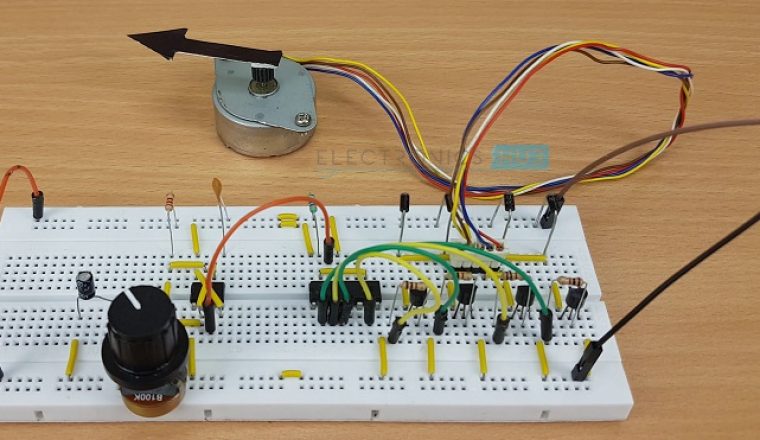
In this project, we have designed a simple 12V Stepper Motor Driver Circuit using 555 Timer IC (acting as a controller), a CD4017 Decade Counter (acting as the driver) along with few other components.
Components Required
CD4017 Decade Counter IC
CD4017 is a Counter IC that produces 10 Decoded outputs and hence a Decade Counter. These counters are often used in displays, frequency division operations, binary counters, etc.
But in this project, we are using the CD4017 Counter IC as a Stepper Motor Driver. And hence, this Stepper Motor Driver Circuit is essentially a Binary Counter Circuit.
Stepper Motor
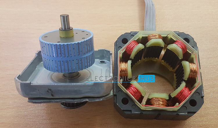
A 12V Stepper Motor is used in this project. It is a Unipolar type Stepper Motor with 5 – wire configuration. Basically, Stepper Motors are classified in to Unipolar Stepper Motors and Bipolar Stepper Motors, based on the windings of the stator. The following image shows a Bipolar Stepper Motor with its winding.
The Driver circuit for a Unipolar Stepper Motor can be constructed with the help of few transistors or a Darlington Transistor IC like ULN2003.
But, the driver circuit for a Bipolar Stepper Motor requires an H – bridge type connection. Hence, we use H – bridge ICs like L293D to drive Bipolar Stepper Motors.
Circuit Design
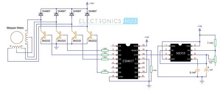
We will start with the Square wave Generator i.e. 555 IC in Astable Mode. A 2.2 KΩ Resistor is connected between the VCC and Discharge Pin of 555 (Pin 7).
A 100 KΩ Potentiometer is connected between the Discharge Pin (Pin 7) and the Threshold pin (Pin 6), which is in turn shorted with the Trigger Pin (Pin 2).
A 1 µF Capacitor is connected between the Trigger pin (Pin 2) and GND. A Bypass Capacitor of 100 pF is connected at the Control Voltage Pin (Pin 5). The other pins i.e. VCC (Pin 8) is connected to 12V supply, Reset Pin (Pin 4) to 12V supply and Ground Pin (Pin 1) to GND.
The Output of 555 Timer IC i.e. the Pin 3 is given as Clock Input to the CD4017 Counter IC i.e. to its 14th Pin. The VDD and VSS pins of CD4017 i.e. Pin 16 and 8 are connected to 12V Supply and GND respectively. Enable Pin (Pin 13) is connected to ground.
We need to control the 4 coil terminals of two coils in the stepper motor. Hence, we need only 4 outputs from the driver. These outputs are Q0 to Q3 i.e. Pins 3, 2, 4 and 7 respectively. The outputs of the Counter are connected to base terminals of 4 transistors through separate 1 KΩ Resistors.
The counter must reset on the fifth pulse and hence the Q4 (Pin 10) which in nothing but the fifth output, is connected to the reset pin of CD4017 i.e. pin 15 and this pin is connected to GND through a 470 Ω Resistor.
The Stepper Motor is a Unipolar Type in 5 wire configuration. The center pin is shorted internally and is connected to the supply (12V here).
The other 4 terminals of the stepper motor are the ends of two coils. They must be connected to the collector terminals of the four transistors.
It important that they are connected in the sequence of firing of the outputs. Finally, four diodes are connected between the collector terminals and supply. Diodes are very important as they will protect the transistors from inductive spiking.
Working of the Stepper Motor Driver Circuit
The working of this Stepper Motor Driver circuit is very simple. We will see a step – by – step working explanation.First, the 555 Timer IC is configured as an Astable Multivibrator i.e. it acts as a square wave generator.
Based on the position of the Potentiometer, the frequency of the square wave will vary anywhere between 7 Hz to 340 Hz.
This square wave is given to the CD4017 Counter IC as its Clock Input. For every positive transition of the clock signal i.e. a low to high transition, the counter output advances by one count.
For first positive transition on clock, Q0 will be high, for second positive transition, Q1 will be high and so on.
Since we need only 4 outputs, the fifth output i.e. Q4 is connected to the Reset pin so that the counter will reset and the counting starts once again.
The outputs of the Counter IC CD4017 are given to 4 different transistor, which are in turn connected to the 4 coil terminals of the Stepper Motor. We can understand better from the following diagram.
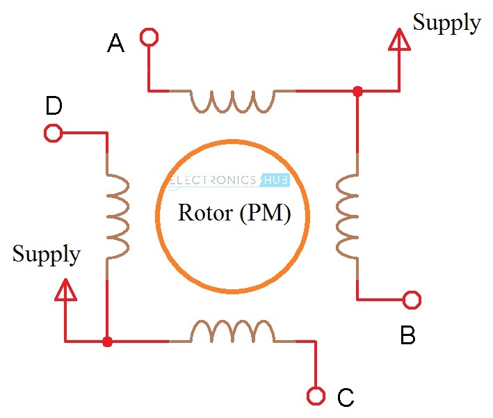 Assume the points A, B, C and D are the contacts of the coils connected to the transistors. The common wire in the stepper motor is given to 12V supply.
When the first clock signal is applied to the CD4017, Q0 becomes HIGH. This will turn ON the corresponding Transistor.
As a result, the supply from the common wire goes through point A to ground. This will energize the coil and acts as an electromagnet. The rotor will get attracted and turns to that position.
During the second clock pulse, output Q1 become HIGH and as a result, the transistor associated with it is turned ON. Now, the current flows from common wire to GND through point B.
Hence, this coil will be energized and turns in to an electromagnet. This will further rotate the rotor. This process continues and depending on the frequency of the clock signal, the speed of rotation of the stepper motor varies.
Advantages
Disadvantages
Source: electronicshub.orgComments
