- Blog entry posted in 'How to wire a switch to an MCU w pullup resistors', December 20, 2016.
by Scott Thornton
If you want a button or switch as an input on a microcontroller (MCU), you can use a “pullup resistor” so that the input is seen as a logical high when the (normally open) switch or button is closed. A pullup resistor is connected to Vcc, or logical high for your input, and therefore “pulls up” the value on the pin to high. The corresponding program or software will need to match the state of a normally open (N.O.) switch as high when the switch is closed. “Normally open” is just that; its natural state is open until you close the switch.
For some MCUs, the MCU itself may run at a different supply voltage (e.g., where Vcc = 5v) than what is used for the inputs (e.g., 3.3v), so make sure you know what your pins can handle. You would connect the pullup resistor like this on an Arduino UNO:
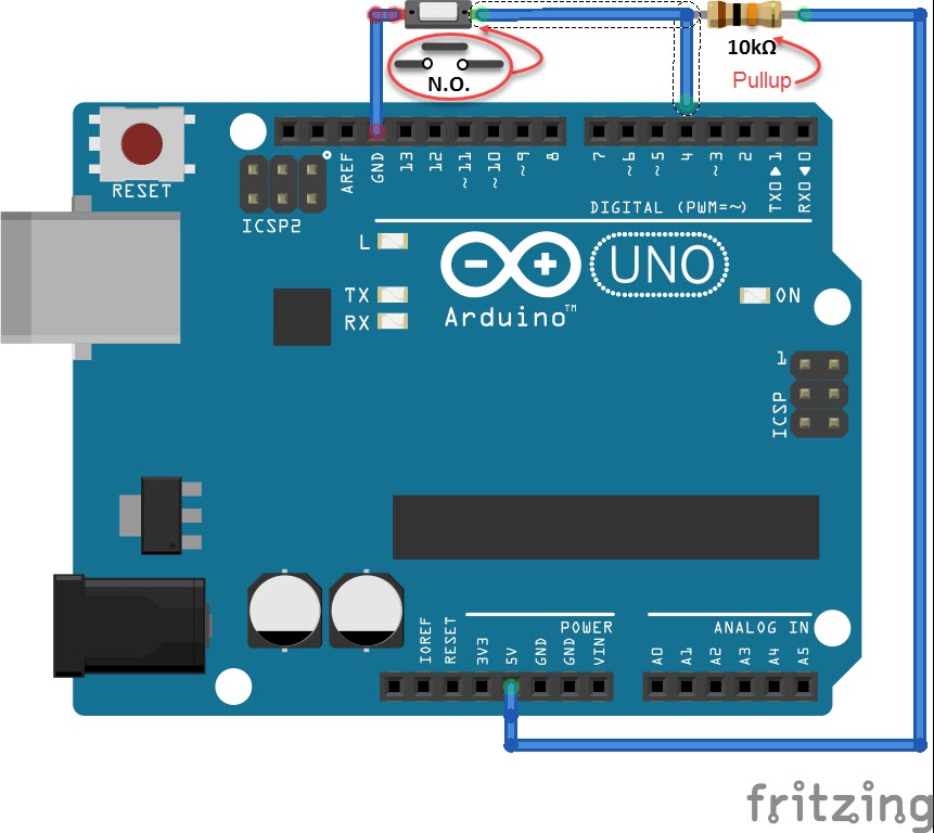
Figure 1: A pull-up resistor on digital input 4 of an Arduino UNO Rev 3. (Drawn using free tool at fritzing.org)
If you have no pullup resistor, your input will still read a state, but whether it will read high or low is unknown, since nothing is physically assigned to it. The exception is if your MCU has an internal pull-up resistor. When nothing is tied to a pin, it’s commonly referred to as a “floating pin,” because it has no assigned state of high/low, and noise can randomly influence the voltage level on the pin if it’s left floating.
In Figure 1, if you press the button, the pin will be connected to ground, and the only reason it doesn’t short ground to the 5v supply is because of the pullup resistor. When the button is open in its normal state, your input sees near the 5v (there is a negligible drop across the pullup resistor.)
What value of pullup resistor do you use? That depends on the MCU. In general, you would use a pullup resistor that is an order of magnitude lower than the input impedance that’s declared in the MCU’s datasheet (in the case of the UNO board, that would be the ATmega328P datasheet.) For our example with an Arduino UNO above, a 10kΩ pullup is recommended.
Pulldown resistors are the same impedance value, but connected just the opposite as a pullup; the resistor is connected to ground and the input is pulled low. The corresponding software would need to reflect the difference and the operation of the switch as normally open or normally closed would also factor into the logic of the whole set up.
The post FAQ: How to wire a switch to a microcontroller with pullup resistors appeared first on Microcontroller Tips.
