- Blog entry posted in 'Electronics-engineering', July 05, 2017.
This is small integrated amplifier that many people link it. We use one TDA2004 or TDA2005 IC to increate very nice sound for really beginner.
– Many of you would have made a small amplifier. With low are expanding. But the sense that sound loud not satisfied. Need to look for higher power amplifiers.
– This the amplifier series, able to respond the demand by are expanding to 20 watt. You can adjust the volume, bass, and treble as needed, plus not too expensive.
How it works
The heart of this project following as figure circuits, at number IC1 TDA2005 (and TDA2004 are used interchangeably). That is IC use for the stereo amplifier, inside comprise of two op-amp that both is connected with the bridge model for power increate up. And it can use to DC power supply 12 volt. And importance it is able to response frequency from 35 Hz to 15 KHz.
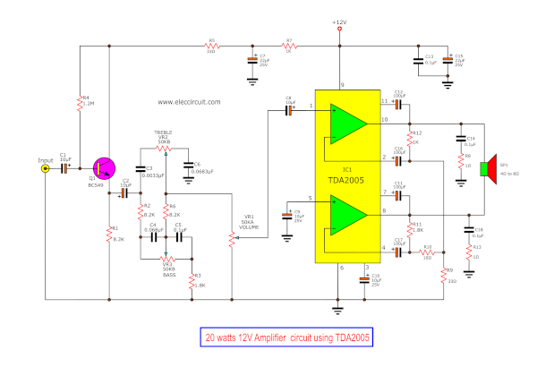
when we know IC1 (TDA2005) is sufficient, following the principles of the overall circuits. Start a input signal will be into this circuit through the capacitor C1 Before, this signal is amplified by transistor Q1. Which capacitors C2,C3,C6 and potentiometer VR2 adjusts the signal level or the high frequency sound.
The capacitor C4,C5 and potentiometer VR3 is defined a Level of the low frequency or bass sound. The signals through VR1 to adjust the size of the signal to be sent enlarge, with be coupling through capacitor C8 to the input pin 1 of IC1, to Enlarge next sign.
– This gain is set with resistors R9, R10 and R12.
– Two capacitor C12 and C11 both are boost trapping to low frequency.
– C17 is a feed back) and set the low frequency.
– C14,R8 and C18,R13 are Prevent high frequency modulating oscillator.
– The output of this circuit at pin 8 and pin 10 of IC1.

– The power supply of this project we use +DC12V. If you do not have may will a power supply for their own use. As shown the Second Circuit that is simple circuit have the transformer Lower voltage 220VAC down to 12VAC and use the diode to connected in bridge rectifier is convert the ACV to DCV , by capacitor C1 to filter To help smooth the DC voltage. The capacitor C2 reduces noise caused by high frequency.
How to build
You soldering electronic components onto the PCB layout.
My son clean the legs of electronic components. To can solder them easier and good.
Starting from power lines, followed by a slower device, the resistor, capacitor, transistor and important IC1.
– Check the connector of the device as well Do not use the soldering iron tip and soak the feet for too long a device, the device may will damaged.
The heat sink of IC1 should be sized appropriately. (Not too small), the IC1 screw tightly.
– Another important thing are Tech of the shield or the ground. If a metal such as the potentiometer and the body of the IC, body should be connected to ground, preventing interference well.
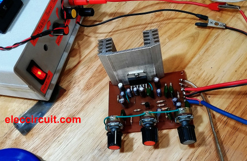
He is testing this project as 20watt Integrated Amplifier by TDA2005.
He use the old small speaker in 8 oms size so well sound for mini rooms.
Note:
Source: eleccircuit.com
