Introduction and Overview
The Secret Knock Detector project is a variation of Steve Hoefer’s Secret Knock Detecting Door Lock, which is featured on Grathio Labs. The original project used an Arduino microcontroller board to sense knocks on a door, and to compare the timing ratio between knocks to a secret knock that was previously recorded. If the timing was correct, the device would engage a small geared motor that would turn the knob on a deadbolt, thus unlocking the door. If the knock was incorrect, it would reset and wait for another knock.
The idea behind this knock detector is the same. However, an Arduino microcontroller was not available, and the thought was that it would be an interesting challenge to adapt the project to use a PIC microcontroller instead. In order to make this work, it was necessary to scrap the original Arduino code and re-write it, and to adapt the circuitry to use the PIC.
This project has a wide variety of potential applications, including simple security for an office, bedroom, or a school dormitory room, geo-tracking stations, or anything else that might require a simple security system. These devices can also be used for a variety of toy applications, conversation pieces, or an assortment of other knock detecting gadgets.
Operation
The heart and brain of the device is a PIC18F1330 microcontroller, which reads the electrical signals from a piezo sensor that is mounted to a door. The piezo sensor is used in two different modes for this project. It works by turning mechanical vibrations into electrical signals, which can be read by the analog-digital converter on the chip, and can also turn electrical signals back into vibrations. This means that the piezo can be used as either a type of microphone or as a speaker. The knock detector utilizes the piezo in both types of operation. When a person knocks on the door, he or she creates several small vibrations which are picked up by the sensor. The chip’s ADC converts the analog voltage signals from the piezo to digital signals, which the chip can read and operate upon. The chip is also able to send electrical signals back to the piezo, which will create audible feedback for the knock.
The device operates as follows: The user presses and holds the red program button until the red LED lights and remains lit. The user knocks on the door in a “secret” pattern. For each knock, the green LED flashes once, indicating the knock was received properly. If no knocks are sensed for three full seconds, the “program” sequence times out and the piezo plays back the knock. The chip then starts listening for a regular knock.
When the piezo senses another vibration, the red LED flashes and the device starts recording the time between the knocks. Again, if the piezo does not receive a signal within three seconds, the listening sequence times out and the chip compares the sensed knock pattern, which was just recorded, to that which was previously programmed. If it matches, the piezo plays a positive-sounding sequence of beeps, and the chip energizes a motor which turns the deadbolt knob and unlocks the door. If it is incorrect, the piezo plays a negative-sounding sequence of beeps, and the chip returns to listening status.
Design and Construction
The first necessary step was to design the schematic for the project. At the time, only the PIC18F1330 processor was available, so that is the chip around which this circuit was constructed. Once designed, it was determined that a custom printed circuit board would be needed, as standard perforated circuit board material would not only look unprofessional, but would also be very difficult to troubleshoot. For this reason, the schematic drawn in EAGLE was also transferred to a PCB layout editor. Prior to having the custom PCBs, all testing took place on a solderless breadboard with used components. With the layout printed neatly onto a circuit board, construction and operation was much neater and the space was used more efficiently. The final Knock Detector EAGLE .sch and .brd files can be found attached to this article.
Once the schematic and board were designed, it was time to work on the programming for the chip. MPLab IDE v8.63 and the C18 compiler were used to create the program. The first attempt at the code was extremely unrefined. Various new concepts were learned and the mistakes were corrected for the final version. The program was broken up into different pieces for ease of programming. For example, a section to sense the knock, a section to compare it to one previously recorded, and a section to unlock the door, were all programmed separately. This allowed for piecewise testing and for easier troubleshooting if something went wrong. For this project, it was necessary to learn how to use the analog-digital converter that was built into the chip, as well as how to use nested arrays and various other aspects of PIC programming and the C language. By breaking the programming up into smaller sections, it was possible to put more focus on individual pieces and to develop a better understanding of each area.
Eventually, the chip was successfully programmed to read a knock correctly using the ADC, and to give a visual response (a flashing LED) to signal that the sensor received the knock. Once that part was completed, it was possible to move on to the next step: saving the timing values to an array. It took several attempts to properly program this section, as the use of nested arrays was particularly difficult to master. From there, all that was needed was to write a function that could save both the sensed knock and the original programmed knock into separate arrays. A few extra features were also added to the programming, which included visual feedback for each knock, as well as audible beeps that signified whether the sensed knock pattern was correct or incorrect.
During the programming process, the EAGLE .brd files were sent to TBS Circuits—the company selected to manufacture the PCBs. The boards arrived in the mail after only three days, having already been tested by the company. Once acquired, one board was immediately populated, and it was finally time to operate the circuit in the field for which it was designed. Unfortunately, a proper project enclosure was not available at this point, so the device was simply duct-taped to a door, with the sensor taped flat against it. A basic desktop demonstration video can be found here.
Conclusion
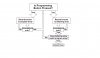
The project is an excellent intermediate-level venture that provides the builder with a stronger understanding of PIC microcontrollers, analog-to-digital converters, and various hardware/software programming techniques. The EAGLE files, a flowchart for the C program, and a block diagram for the circuit are attached to this article.
Feel free to experiment with the setup. Eventually the board will be miniaturized in order to cut costs and to increase efficiency. You are free to use the designs included for your own use, and please do not hesitate to improve upon them. Hopefully this article has inspired you to experiment with microcontrollers and programming, and has given some insight into the vast field of microcontroller programming. Good luck in your own ventures, and most importantly, have fun!
Thanks
I’d like to offer my personal thanks to all the members here at Electro-Tech-Online who helped me with this project. Special thanks go out to 3v0 whom, I must say, helped the most with the programming process. I would not have been able to finish this project without his assistance.
The PCB for the knock detector was manufactured by the guys at TBS Circuits. If you ever need boards made for a project, I highly recommend them. Their work is top-notch, competitively priced, and their shipping times are extraordinary. A huge thank you goes out to them!
UPDATE: I have been informed that due to the recent hard drive failure, the links to the sch and brd files no longer work. I have replaced the png files, but am currently unable to replace the EAGLE designs. Sorry for the inconvenience.
UPDATED UPDATE: The links to the .sch and .brd files should be fixed. Thanks for your patience.
The Secret Knock Detector project is a variation of Steve Hoefer’s Secret Knock Detecting Door Lock, which is featured on Grathio Labs. The original project used an Arduino microcontroller board to sense knocks on a door, and to compare the timing ratio between knocks to a secret knock that was previously recorded. If the timing was correct, the device would engage a small geared motor that would turn the knob on a deadbolt, thus unlocking the door. If the knock was incorrect, it would reset and wait for another knock.
The idea behind this knock detector is the same. However, an Arduino microcontroller was not available, and the thought was that it would be an interesting challenge to adapt the project to use a PIC microcontroller instead. In order to make this work, it was necessary to scrap the original Arduino code and re-write it, and to adapt the circuitry to use the PIC.
This project has a wide variety of potential applications, including simple security for an office, bedroom, or a school dormitory room, geo-tracking stations, or anything else that might require a simple security system. These devices can also be used for a variety of toy applications, conversation pieces, or an assortment of other knock detecting gadgets.
Operation
The heart and brain of the device is a PIC18F1330 microcontroller, which reads the electrical signals from a piezo sensor that is mounted to a door. The piezo sensor is used in two different modes for this project. It works by turning mechanical vibrations into electrical signals, which can be read by the analog-digital converter on the chip, and can also turn electrical signals back into vibrations. This means that the piezo can be used as either a type of microphone or as a speaker. The knock detector utilizes the piezo in both types of operation. When a person knocks on the door, he or she creates several small vibrations which are picked up by the sensor. The chip’s ADC converts the analog voltage signals from the piezo to digital signals, which the chip can read and operate upon. The chip is also able to send electrical signals back to the piezo, which will create audible feedback for the knock.
The device operates as follows: The user presses and holds the red program button until the red LED lights and remains lit. The user knocks on the door in a “secret” pattern. For each knock, the green LED flashes once, indicating the knock was received properly. If no knocks are sensed for three full seconds, the “program” sequence times out and the piezo plays back the knock. The chip then starts listening for a regular knock.
When the piezo senses another vibration, the red LED flashes and the device starts recording the time between the knocks. Again, if the piezo does not receive a signal within three seconds, the listening sequence times out and the chip compares the sensed knock pattern, which was just recorded, to that which was previously programmed. If it matches, the piezo plays a positive-sounding sequence of beeps, and the chip energizes a motor which turns the deadbolt knob and unlocks the door. If it is incorrect, the piezo plays a negative-sounding sequence of beeps, and the chip returns to listening status.
Design and Construction
The first necessary step was to design the schematic for the project. At the time, only the PIC18F1330 processor was available, so that is the chip around which this circuit was constructed. Once designed, it was determined that a custom printed circuit board would be needed, as standard perforated circuit board material would not only look unprofessional, but would also be very difficult to troubleshoot. For this reason, the schematic drawn in EAGLE was also transferred to a PCB layout editor. Prior to having the custom PCBs, all testing took place on a solderless breadboard with used components. With the layout printed neatly onto a circuit board, construction and operation was much neater and the space was used more efficiently. The final Knock Detector EAGLE .sch and .brd files can be found attached to this article.
Once the schematic and board were designed, it was time to work on the programming for the chip. MPLab IDE v8.63 and the C18 compiler were used to create the program. The first attempt at the code was extremely unrefined. Various new concepts were learned and the mistakes were corrected for the final version. The program was broken up into different pieces for ease of programming. For example, a section to sense the knock, a section to compare it to one previously recorded, and a section to unlock the door, were all programmed separately. This allowed for piecewise testing and for easier troubleshooting if something went wrong. For this project, it was necessary to learn how to use the analog-digital converter that was built into the chip, as well as how to use nested arrays and various other aspects of PIC programming and the C language. By breaking the programming up into smaller sections, it was possible to put more focus on individual pieces and to develop a better understanding of each area.
Eventually, the chip was successfully programmed to read a knock correctly using the ADC, and to give a visual response (a flashing LED) to signal that the sensor received the knock. Once that part was completed, it was possible to move on to the next step: saving the timing values to an array. It took several attempts to properly program this section, as the use of nested arrays was particularly difficult to master. From there, all that was needed was to write a function that could save both the sensed knock and the original programmed knock into separate arrays. A few extra features were also added to the programming, which included visual feedback for each knock, as well as audible beeps that signified whether the sensed knock pattern was correct or incorrect.
During the programming process, the EAGLE .brd files were sent to TBS Circuits—the company selected to manufacture the PCBs. The boards arrived in the mail after only three days, having already been tested by the company. Once acquired, one board was immediately populated, and it was finally time to operate the circuit in the field for which it was designed. Unfortunately, a proper project enclosure was not available at this point, so the device was simply duct-taped to a door, with the sensor taped flat against it. A basic desktop demonstration video can be found here.
Conclusion
The project is an excellent intermediate-level venture that provides the builder with a stronger understanding of PIC microcontrollers, analog-to-digital converters, and various hardware/software programming techniques. The EAGLE files, a flowchart for the C program, and a block diagram for the circuit are attached to this article.
Feel free to experiment with the setup. Eventually the board will be miniaturized in order to cut costs and to increase efficiency. You are free to use the designs included for your own use, and please do not hesitate to improve upon them. Hopefully this article has inspired you to experiment with microcontrollers and programming, and has given some insight into the vast field of microcontroller programming. Good luck in your own ventures, and most importantly, have fun!
Thanks
I’d like to offer my personal thanks to all the members here at Electro-Tech-Online who helped me with this project. Special thanks go out to 3v0 whom, I must say, helped the most with the programming process. I would not have been able to finish this project without his assistance.
The PCB for the knock detector was manufactured by the guys at TBS Circuits. If you ever need boards made for a project, I highly recommend them. Their work is top-notch, competitively priced, and their shipping times are extraordinary. A huge thank you goes out to them!
UPDATE: I have been informed that due to the recent hard drive failure, the links to the sch and brd files no longer work. I have replaced the png files, but am currently unable to replace the EAGLE designs. Sorry for the inconvenience.
UPDATED UPDATE: The links to the .sch and .brd files should be fixed. Thanks for your patience.