Resistors or linear constant-current sources are usually okay to establish the current in small, low-current LEDs, but for high power LEDs, the power losses of such schemes can be problematic, from both efficiency and power dissipation considerations, so a higher efficiency, constant-current, switching supply is preferable.
There are dedicated IC SMPS (Switched Mode Power Supply) chips to do that, but here's a converter that uses the common LM339/393 comparators and CD4050 buffers as part of a fairly simple, high efficiency circuit. It doesn't have all the bells and whistles of a dedicated IC but it's a simple design that should work well enough for the do-it-yourselfer who might not have ready access to the dedicated chips.
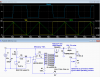
Below is the LTspice simulation of the regulator for LEDs up to about 10A (simulation is running at 10A).
It's a hysteretic (bang-bang) feedback type which is simple and requires no feedback compensation.
Such regulators can have higher ripple than a standard linear feedback buck regulator, but high frequency ripple is generally not a concern for LEDs used for illumination.

The comparator detects the voltage across the shunt resistor R1 due to the inductor/LED current, and when it drops below the Set voltage, its output goes low and turns on the P-MOSFET, M1, through the CD4050 non-inverting buffer.
The inductor/LED current then increases until the R1 voltage goes above the set voltage, causing the comparator output to go high, turning off M1.
The operating frequency and hysteresis ripple current is determined by the relative value of R6 and R7, the switching speed of the comparator, and the inductance value of L1.
The simulation for the values shown give an operating frequency of 35kHz.
The simulated efficiency of the circuit is about 90% at a 10A LED current with a white, 20A maximum LED that has about a 4V drop.
The actual circuit efficiency will likely vary some from this, depending upon the characteristics of the components you actually use.
The LED regulated current is determined by the Set reference voltage as set by pot U3.
Voltage reference U2 provides a stable 2.5V for a constant output current, independent of variations in input voltage and temperature.
R1 should be selected to generate abourt 100mv at the desired LED current for reliable operation.
U3 can be a trimpot if you infrequently need to adjust the current, or a knob-pot if you want a dimmer control.
The 6 non-inverting buffers in a CD4050 package are used in parallel as a poor-man's push-pull, low-impedance, gate driver for P-MOSFET M1, since such a drive is needed to rapidly charge and discharge the large gate capacitance for fast switching of the P-MOSFET, thus minimizing switching losses.
(Power and ground connections for the CD4050 are not shown and must be added.)
These paralleled 4050's don't have the gate drive capability of a dedicated IC gate driver, but it's sufficient for this application, and is generally cheaper and more readily available.
Note that for minimum P-MOSFET dissipation (simulated ≈800mW average), it must have characteristics close to (or better than) the one used in the simulation.
This dissipation is low enough to not require a heatsink for the MOSFET.
MOSFETs with appreciably higher ON resistance and/or gate charge (capacitance) can increase the MOSFET's dissipation to the point where a heatsink would be required.
Due to the high current, the free-wheeling Schottky diode D2 will require a heatsink.
The simulation indicates it will dissipate about 2.5W at a 10A output.
For currents below about 3A, a heatsink is probably not required.
The inductor should be a toroidal type with ratings close to those shown on the schematic.
C1 must be a low ESR capacitor designed to handle the high 10A ripple currents of this circuit.
A standard electrolytic could overheat and blow.
It may be easier to obtain the desired low ESR characteristics by using two or more lower capacitance electrolytics in parallel.
This circuit should be built on a PCB or vector board with a ground plane for proper circuit operation, with the bottom of R1 connected at the reference circuit ground connections.
Building this on a plug-in breadboard will likely result in poor or flaky operation.
There are dedicated IC SMPS (Switched Mode Power Supply) chips to do that, but here's a converter that uses the common LM339/393 comparators and CD4050 buffers as part of a fairly simple, high efficiency circuit. It doesn't have all the bells and whistles of a dedicated IC but it's a simple design that should work well enough for the do-it-yourselfer who might not have ready access to the dedicated chips.
Below is the LTspice simulation of the regulator for LEDs up to about 10A (simulation is running at 10A).
It's a hysteretic (bang-bang) feedback type which is simple and requires no feedback compensation.
Such regulators can have higher ripple than a standard linear feedback buck regulator, but high frequency ripple is generally not a concern for LEDs used for illumination.
The comparator detects the voltage across the shunt resistor R1 due to the inductor/LED current, and when it drops below the Set voltage, its output goes low and turns on the P-MOSFET, M1, through the CD4050 non-inverting buffer.
The inductor/LED current then increases until the R1 voltage goes above the set voltage, causing the comparator output to go high, turning off M1.
The operating frequency and hysteresis ripple current is determined by the relative value of R6 and R7, the switching speed of the comparator, and the inductance value of L1.
The simulation for the values shown give an operating frequency of 35kHz.
The simulated efficiency of the circuit is about 90% at a 10A LED current with a white, 20A maximum LED that has about a 4V drop.
The actual circuit efficiency will likely vary some from this, depending upon the characteristics of the components you actually use.
The LED regulated current is determined by the Set reference voltage as set by pot U3.
Voltage reference U2 provides a stable 2.5V for a constant output current, independent of variations in input voltage and temperature.
R1 should be selected to generate abourt 100mv at the desired LED current for reliable operation.
U3 can be a trimpot if you infrequently need to adjust the current, or a knob-pot if you want a dimmer control.
The 6 non-inverting buffers in a CD4050 package are used in parallel as a poor-man's push-pull, low-impedance, gate driver for P-MOSFET M1, since such a drive is needed to rapidly charge and discharge the large gate capacitance for fast switching of the P-MOSFET, thus minimizing switching losses.
(Power and ground connections for the CD4050 are not shown and must be added.)
These paralleled 4050's don't have the gate drive capability of a dedicated IC gate driver, but it's sufficient for this application, and is generally cheaper and more readily available.
Note that for minimum P-MOSFET dissipation (simulated ≈800mW average), it must have characteristics close to (or better than) the one used in the simulation.
This dissipation is low enough to not require a heatsink for the MOSFET.
MOSFETs with appreciably higher ON resistance and/or gate charge (capacitance) can increase the MOSFET's dissipation to the point where a heatsink would be required.
Due to the high current, the free-wheeling Schottky diode D2 will require a heatsink.
The simulation indicates it will dissipate about 2.5W at a 10A output.
For currents below about 3A, a heatsink is probably not required.
The inductor should be a toroidal type with ratings close to those shown on the schematic.
C1 must be a low ESR capacitor designed to handle the high 10A ripple currents of this circuit.
A standard electrolytic could overheat and blow.
It may be easier to obtain the desired low ESR characteristics by using two or more lower capacitance electrolytics in parallel.
This circuit should be built on a PCB or vector board with a ground plane for proper circuit operation, with the bottom of R1 connected at the reference circuit ground connections.
Building this on a plug-in breadboard will likely result in poor or flaky operation.