With many power supplies now being microprocessor based it is desirable to have simple way to control the voltage output of the supply from the μP.
An easy way to do that is with a PWM signal that most μPs can readily generate.
This signal can be averaged to give a DC output voltage to control the regulator.
The accuracy of PWM is not high, but most digital based supplies have digital readouts, allowing good accuracy setting of the voltage.
If high control accuracy is desired, the regulator output voltage can be sampled by an A/D converter in the μP, and the PWM duty-cycle adjusted accordingly.
Many standard IC regulators can be controlled in this manner, whose output voltage is normally determined by a resistor or two. These regulators are simple and rugged, generally having overcurrent and over-temperature protection. They also provide good regulation, maintaining the set voltage over a wide range of input voltage, temperature, and output current changes.
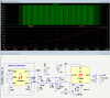
Below is the LTspice simulation of a 5V PWM signal controlling an LT3080 regulator, configured for a 15V maximum output.
An LTC6992 is used to generate the PWM. simulating the μP's output.
The LT3080 output goes from 0V to about 14V as the PWM signal goes from 0% to 100% duty-cycle, with a 15V supply.
The LT3080 is a low-dropout regulator that can be adjusted down to 0V out, which is not common.
Most IC regulators can only go down to about 1.25V minimum.

U3 is a 3-pole Bessel filter, which has the desired response of minimal overshoot with a step voltage change, using a common LM324/LM358 op amp.
It has a 12Hz corner and a 60ms settling time to better than 1%, which averages and smooths the PWM pulses, giving a 0 to 5Vdc output for a 5V, 0-100% duty-cycle PWM input.
One of the reasons for using this 3-pole filter design is that it has a passive RC first stage to roll off the high frequency edges of the square-wave. Otherwise those edges can feed directly to the output through C2, since the standard op amp used isn't fast enough to roll off those high frequencies through that feedback path. This edge spike feedthrough was seen during simulations of a 2-pole Sallen-Key filter.
The filter output is amplified by the non-inverting amp U4 with a gain of 3 to give the (nearly) 15V output.
The filter rolloff frequency and the amp gain are determined by the PWM frequency and the input to output voltage gain required.
(The simulation used a 550Hz PWM frequency, in the ballpark of Arduino PWM outputs).
It might be noted that the PWM duty-cycle to voltage accuracy is affected by the PWM pulse voltage, since that voltage is being averaged to get the output voltage.
Thus for good regulator output voltage accuracy, the supply voltage for the μP generating the PWM signal needs to be well regulated.
If the LT3080 is too expensive for your application, this circuit also works with common three terminal regulators, such as the ubiquitous LM317, the tradeoff being that the minimum output is 1.25V instead of 0V, and the maximum output is about 1V less.
Simulation with an LM317 below:

An easy way to do that is with a PWM signal that most μPs can readily generate.
This signal can be averaged to give a DC output voltage to control the regulator.
The accuracy of PWM is not high, but most digital based supplies have digital readouts, allowing good accuracy setting of the voltage.
If high control accuracy is desired, the regulator output voltage can be sampled by an A/D converter in the μP, and the PWM duty-cycle adjusted accordingly.
Many standard IC regulators can be controlled in this manner, whose output voltage is normally determined by a resistor or two. These regulators are simple and rugged, generally having overcurrent and over-temperature protection. They also provide good regulation, maintaining the set voltage over a wide range of input voltage, temperature, and output current changes.
Below is the LTspice simulation of a 5V PWM signal controlling an LT3080 regulator, configured for a 15V maximum output.
An LTC6992 is used to generate the PWM. simulating the μP's output.
The LT3080 output goes from 0V to about 14V as the PWM signal goes from 0% to 100% duty-cycle, with a 15V supply.
The LT3080 is a low-dropout regulator that can be adjusted down to 0V out, which is not common.
Most IC regulators can only go down to about 1.25V minimum.
U3 is a 3-pole Bessel filter, which has the desired response of minimal overshoot with a step voltage change, using a common LM324/LM358 op amp.
It has a 12Hz corner and a 60ms settling time to better than 1%, which averages and smooths the PWM pulses, giving a 0 to 5Vdc output for a 5V, 0-100% duty-cycle PWM input.
One of the reasons for using this 3-pole filter design is that it has a passive RC first stage to roll off the high frequency edges of the square-wave. Otherwise those edges can feed directly to the output through C2, since the standard op amp used isn't fast enough to roll off those high frequencies through that feedback path. This edge spike feedthrough was seen during simulations of a 2-pole Sallen-Key filter.
The filter output is amplified by the non-inverting amp U4 with a gain of 3 to give the (nearly) 15V output.
The filter rolloff frequency and the amp gain are determined by the PWM frequency and the input to output voltage gain required.
(The simulation used a 550Hz PWM frequency, in the ballpark of Arduino PWM outputs).
It might be noted that the PWM duty-cycle to voltage accuracy is affected by the PWM pulse voltage, since that voltage is being averaged to get the output voltage.
Thus for good regulator output voltage accuracy, the supply voltage for the μP generating the PWM signal needs to be well regulated.
If the LT3080 is too expensive for your application, this circuit also works with common three terminal regulators, such as the ubiquitous LM317, the tradeoff being that the minimum output is 1.25V instead of 0V, and the maximum output is about 1V less.
Simulation with an LM317 below: