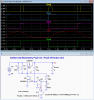
Here is a simple, high-side power switch that requires only 1 N-MOSFET, 1 P-MOSFET, 3 resistors, 2 capacitors and a momentary PB for control.
It is insensitive to the length of time the PB is pressed and also to any normal switch bounce.
The OFF power draw is only the circuit leakage current.
S1 and V1 simulate the momentary PB switch. For simulation purposes it is shown with an ON time of 100ms and a period of 1 second.
C1 provides the debounce delay and also feedback delay to allow proper switching of the circuit.
C2 insures that the circuit will come up in the OFF state when power is initially applied to the circuit. If that is not needed then C2 can be eliminated.
For supply voltages below 10V the MOSFETs must be logic-level types that turn ON fully (not their Vgs threshold) at the supply voltage (the Vgs value where the Ron is measured in the data sheet).
For supply voltages above the maximum MOSFET Vgs (typically 20V) you will need to add circuitry to limit Vgs to the transistor limit (normally an added voltage divider resistor in the series with the drain of M2 and from M2's gate to ground will do).
The MOSFETs can be just about any that meet the current and voltage requirements of the application.
The maximum current it can switch is basically limited only by the current capacity of the P-MOSFET, M1 (and any heat sinking it may require for higher currents).
The N-MOSFET, M2 carries only a mA of current so can be a low-power device, such as the 2N7000 shown.
For voltages less than 20V a CD4049B inverter could be substituted for M2.
With that you don't need R1, and it should also come up in the power OFF state without C2.
I don't know the origins of the circuit but the basic design was apparently posted by BIFF383 on the All About Circuits Forum.
I had to modify some of the resistor values to get good switching levels so I decided post it here with the simulation to document its operation.