The Basic use of a pull-up or pull-down resistor is to prevent a 'floating' input to a digital circuit.
Pull Up and Pull Down Resistors. Ver1.0
Part 1. CMOS Inputs.
Due to the very high input resistance of a CMOS input pin, the pin, if not connected to an external source will have an indeterminate state. Sometimes referred to as ‘floating’
On most PIC’s, which use internal diode clamps to +Vdd and 0V, the indeterminate state is anywhere between these two voltage limits.
A ‘PU’ pull up or ‘PD’ pull down resistor is solely used for holding [pulling] the unconnected input pin of a PIC or IC, to either +Vdd or at 0V.
A ‘PU’ would be connected from the input pin to +Vdd and
a ‘PD’ connected from the input pin to 0V.
The value of the resistor is usually between 1K and 10K.
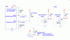
An example where a input pin could be in a disconnected ‘floating’ state is when used with an external switch,Refer Fig #1
Assume a normally open [n/o] push switch connected between the input pin and 0V, without a pull up resistor.
When the switch is not operated, the input is effectively disconnected, so the input pin state is indeterminate, [floating]
With a pull up resistor to +Vdd on the input pin the pin would be at +Vdd when the switch is not operated and at 0V when operated.
So the input pin never becomes disconnected ie: floating.
Its also possible to have a pull down resistor on an input pin. In this case the push switch would be connected from the input pin to +Vdd.
So when the switch is not operated, the input pin is at 0V and when the switch is operated the input pin is at +Vdd.
Note:
De-bouncing of the switch contact action is not the purpose of a PU or PD resistor
Unused inputs on CMOS logic can be connected directly to 0V.
Do NOT connect unused outputs directly to +Vdd or 0V, they can be left disconnected.

Part 2A. Open Collector/Drain Outputs.
Some types of IC's have what are called open Collector [Transistor] or open Drain [FET] Outputs. Refer Fig #2
This means there will no measurable voltage on this type of pin without a pull up resistor.
In order to use a open type output a pull up resistor is required from the output pin to +V
The resistive value of the pull up is chosen to suit the current/voltage sink current rating of the devices output pin.
Often the specified working voltage rating of an open collector/drain can be a lot higher than the +Vdd required by the device.
Part 2B. Open Emitter/Source Outputs.
There are also devices with open Emitter [Transistor] or open Source [FET] outputs.
This type of output pin requires a pull down resistor to 0V. The value of the resistor is chosen to suit the voltage/current source current of the devices output pin.
Note: there are number of analog comparators that have an open collector/drain output and so require a pull up resistor to +V.
examples are the LM393 and LM311.
Other Applications where a PU or PD Resistor is Used.
The term pull up resistor is used in Digital circuits that share a common Address lines [bus], or bi-directional Data bus lines.
By using a PU resistor on a shared line, open circuit outputs from a number of devices can be Or'd together in order to control or place Data signals on the same line.
...................
Pull Up and Pull Down Resistors. Ver1.0
Part 1. CMOS Inputs.
Due to the very high input resistance of a CMOS input pin, the pin, if not connected to an external source will have an indeterminate state. Sometimes referred to as ‘floating’
On most PIC’s, which use internal diode clamps to +Vdd and 0V, the indeterminate state is anywhere between these two voltage limits.
A ‘PU’ pull up or ‘PD’ pull down resistor is solely used for holding [pulling] the unconnected input pin of a PIC or IC, to either +Vdd or at 0V.
A ‘PU’ would be connected from the input pin to +Vdd and
a ‘PD’ connected from the input pin to 0V.
The value of the resistor is usually between 1K and 10K.
An example where a input pin could be in a disconnected ‘floating’ state is when used with an external switch,Refer Fig #1
Assume a normally open [n/o] push switch connected between the input pin and 0V, without a pull up resistor.
When the switch is not operated, the input is effectively disconnected, so the input pin state is indeterminate, [floating]
With a pull up resistor to +Vdd on the input pin the pin would be at +Vdd when the switch is not operated and at 0V when operated.
So the input pin never becomes disconnected ie: floating.
Its also possible to have a pull down resistor on an input pin. In this case the push switch would be connected from the input pin to +Vdd.
So when the switch is not operated, the input pin is at 0V and when the switch is operated the input pin is at +Vdd.
Note:
De-bouncing of the switch contact action is not the purpose of a PU or PD resistor
Unused inputs on CMOS logic can be connected directly to 0V.
Do NOT connect unused outputs directly to +Vdd or 0V, they can be left disconnected.
Part 2A. Open Collector/Drain Outputs.
Some types of IC's have what are called open Collector [Transistor] or open Drain [FET] Outputs. Refer Fig #2
This means there will no measurable voltage on this type of pin without a pull up resistor.
In order to use a open type output a pull up resistor is required from the output pin to +V
The resistive value of the pull up is chosen to suit the current/voltage sink current rating of the devices output pin.
Often the specified working voltage rating of an open collector/drain can be a lot higher than the +Vdd required by the device.
Part 2B. Open Emitter/Source Outputs.
There are also devices with open Emitter [Transistor] or open Source [FET] outputs.
This type of output pin requires a pull down resistor to 0V. The value of the resistor is chosen to suit the voltage/current source current of the devices output pin.
Note: there are number of analog comparators that have an open collector/drain output and so require a pull up resistor to +V.
examples are the LM393 and LM311.
Other Applications where a PU or PD Resistor is Used.
The term pull up resistor is used in Digital circuits that share a common Address lines [bus], or bi-directional Data bus lines.
By using a PU resistor on a shared line, open circuit outputs from a number of devices can be Or'd together in order to control or place Data signals on the same line.
...................