This article is about computing the magnetic field outside of a finite straight wire using Biot Savart. It helps to understand the use of Biot Savart like this so that magnetic fields of other wire shapes may be computed such as a loop of wire, inside and outside of the loop. I hope to do more articles on this where we do the loop inside and out.
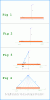
There are two attachments which you'll have to refer to while reading this. The first one shows the set up of the wire and a point outside the wire. There is always a point shown along with the wire because that's the point where we want to get the solution for. The second attachment shows the equations involved. This text will relate how to use the equations with the setup shown in the first attachment.
We start with Fig. 1 in the first attachment. Here we see a wire (orange) and the length is shown as Lw. This means it could be any length. Also shown is the current I, which flows in the direction shown by the arrow in the wire just under the I. The point is shown as P, and the point is at a distance R from the center of the wire where the center is in the middle of the length of the wire. The wire is assumed to be of very tiny diameter even though it is drawn larger in the the figures for clarity.
In Fig. 2 we see the wire was divided in half with half of the length Lw/2 shown to the right side and Lw/2 to the left side of zero. The length is assumed to lie on the x axis as shown with x increasing to the right. This allows us to label the half-length on the right as +Lw/2 and the half-length on the left as -Lw/2. That's because those are the two positions on the x axis.
In Fig. 3 there are a few more things added. The blue arrow labeled 'r' (lower case, bold type) is a vector. The tip of the vector coincides with the point P, and the tail of the vector is directly in the center of a smaller length of the wire which we call 'dL' (bold type). dL is the infinitesimal length vector which is just a smaller part of the wire which later we allow to get very very small.
The idea is to move dL along the wire and while doing that we compute the field at P after each move, and sum all of those results. That gives us the total B at P. The direction of dL never changes, but the direction of r changes as we move the tail along the wire to follow the center of dL.
We also see another length L that measures the distance from the center of the wire to the center of the vector dL.
In Fig. 4 I have drawn several possible positions for the vector r. If we start at -Lw/2 the vector is pointing up and to the right (r1), and as we move the tail along the wire from left to right we eventually get the vector to reach the position shown in as r2. So the vector tail moves along the wire but the tip (point) does not as it stays anchored at the point P. This is one of the key points of Biot Savart. The tip of the vector stays anchored at the solution point P while the tail of the vector follows the center of dL. You'll also note that dL is drawn a little smaller and it is shown at the left end of the wire and at the right end of the wire. That's because dL is moved along the wire with the tail of the vector r following it. This is the second key point to using Biot Savart: the vector dL follows the wire along it's length from the start to the finish (for a loop the start would be the same point as the finish).
To review, the two key points to using Biot Savart are:
1. The vector dL follows the wire.
2. The tail of the vector r follows dL, and the tip stays at P.
So to use Biot Savart we must always identify dL and r first. Then the solution for each position (from r1 to r2 as in Fig. 4) is the cross product of dL and r divided by the length of r squared, times the current I and times a constant. The total B at the point is then just the sum of all of those results using all r from r1 to r2.
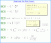
Now on to the equations which appear in the second attachment.
To get a quick view of what is a vector and what is not, see the small rectangular inset just to the right of EQ1 at the top right corner of the attachment. The other things shown there also will be explained shortly.
EQ1: This is the Law of Biot and Savart. It states just what was said above, that the total B is equal to the sum of all the cross products of dL and all r over the length of the wire, divided by the length of r squared, and times the current and times a constant, where the constant is equal to the permeability of free space divided by 4 times pi (as shown just to the left of the integral symbol). The permeability of free space is just a number and so is 4 and so is pi, so that part of it is just a constant. That constant sometimes appears inside the integral but because it does not vary with distance we can take it out of the integral.
EQ2: Here we see the same integral with a slight modification. For one, the current I has been taken out of the integral. Since I is not allowed to change it becomes a constant and so is taken out of the integral, so it is shown with the other constants. Also, the vector r has been changed to appear with a little open bottomed triangle just over top of it. That triangle (usually called just a 'hat') means that we made r a unit vector. It is often denoted as simply "r hat" or "r_hat". To calculate r_hat we see in the inset the calculation is just r over the norm of r, or stated another way, the vector r divided by the length of the vector r. We also see that the norm of r cubed in the denominator (again 'norm' just means the length of r) has been squared instead of cubed. These two modifications, making r the unit vector r_hat and reducing the power of the denominator by 1 came about because when we make r in the numerator the unit vector r_hat we can reduce the power of r in the denominator by 1 to keep the same equality as when we had just r and the norm of r cubed. This is just a slight simplification and does not change the integral.
EQ3: In EQ2 we had the cross product of dL and r in the numerator, so here we now calculate that product. The method being used here is the trigonometric equivalent to the cross product where we don't actually have to do the algebraic cross product. It doesn't make any difference in the solution though, because the two methods are the same in the end. The trig equivalent is shown just to the right of the equals sign. It is just the norm of dL multiplied by the norm of r_hat multiplied by the sine of the angle A, in the direction of the unit normal (don't worry about the unit normal for now). We were forming the cross product of dL and r_hat here, so the angle A is the angle between dL and r_hat.
Now since the norm of r_hat is just 1 (the length of a unit vector is always 1) we can drop that factor and are left with just dL times the sine of the angle A times the unit normal, which is shown just to the right of the second equals sign. Finally on the far right we see that since the norm of dL (dL a vector) is just dL (dL the scalar) we have dL (the scalar) multiplied by sine of angle A and we drop the unit normal because the field vector B is pointing out of the page and that means the equation is now being solved in only one direction, the direction of B, so we don't need to really keep track of the direction anymore. So we are left with:
dL*sin(A)
where dL is just the length of the vector dL here.
EQ4: Here the solution to the cross product found above is inserted into the equation replacing the cross product of dL and r_hat. Nothing else has changed. If we wanted to, we could convert this integral into an integral where we integrate over the angle from the angle of r1 to the angle of r2, but that's not the way we will do it here.
Also note that there are two identities shown in the small inset just to the right of EQ4. These help convert the integral into a purely algebraic form.
EQ5: Here there are some modifications to EQ4. The first factor that appears in the integral is just 1 over the square of r, which looking back at Fig. 3, the length of r can *always* be calculated from:
|r|=sqrt(R^2+L^2)
and this is true because here the L is the variable L which follows the x axis as we move the tail of r across the wire length. The second factor is an algebraic substitution for the trig function sin(A) which is:
sin(A)=y/r
where y is the constant R value and r is sqrt(R^2+L^2) as always. So for our purpose, sin(A) becomes R/sqrt(R^2+L^2), so that replaces sin(A) in the integral. Simplifying a little, we see the final integral just to the right of that.
EQ6:
Now we integrate over the length from -Lw/2 to +Lw/2 and we do it this way because we want the B out from the center of the wire (mid length). If we wanted the B near the end of the wire on the right side, we would integrate from 0 to Lw. But here we want the B out from the center so we integrate from -Lw/2 to +Lw/2.
This equation shows the result of that integration just to the right of the first equals sign, and a slightly different form for the result just to the right of the second equals sign.
So EQ6 (either form) is the final solution which represents the magnetic field B at the point P shown in Fig. 1, and the direction is out of the page following the right hand rule where we curl the fingers of the right hand and point the thumb in the direction of the current, and B points in the direction of the fingers.
It's interesting to note that this solution is for when r is in the plane of the page, but if we tilt r back slightly so the tip (and the point P) goes into the page a little, then B will point out of the page and also slightly upward. If we rotate r around the wire we find that B changes direction all around the wire, but keeps the same magnitude. So B 'curls' around the wire in a circle.
There are two attachments which you'll have to refer to while reading this. The first one shows the set up of the wire and a point outside the wire. There is always a point shown along with the wire because that's the point where we want to get the solution for. The second attachment shows the equations involved. This text will relate how to use the equations with the setup shown in the first attachment.
We start with Fig. 1 in the first attachment. Here we see a wire (orange) and the length is shown as Lw. This means it could be any length. Also shown is the current I, which flows in the direction shown by the arrow in the wire just under the I. The point is shown as P, and the point is at a distance R from the center of the wire where the center is in the middle of the length of the wire. The wire is assumed to be of very tiny diameter even though it is drawn larger in the the figures for clarity.
In Fig. 2 we see the wire was divided in half with half of the length Lw/2 shown to the right side and Lw/2 to the left side of zero. The length is assumed to lie on the x axis as shown with x increasing to the right. This allows us to label the half-length on the right as +Lw/2 and the half-length on the left as -Lw/2. That's because those are the two positions on the x axis.
In Fig. 3 there are a few more things added. The blue arrow labeled 'r' (lower case, bold type) is a vector. The tip of the vector coincides with the point P, and the tail of the vector is directly in the center of a smaller length of the wire which we call 'dL' (bold type). dL is the infinitesimal length vector which is just a smaller part of the wire which later we allow to get very very small.
The idea is to move dL along the wire and while doing that we compute the field at P after each move, and sum all of those results. That gives us the total B at P. The direction of dL never changes, but the direction of r changes as we move the tail along the wire to follow the center of dL.
We also see another length L that measures the distance from the center of the wire to the center of the vector dL.
In Fig. 4 I have drawn several possible positions for the vector r. If we start at -Lw/2 the vector is pointing up and to the right (r1), and as we move the tail along the wire from left to right we eventually get the vector to reach the position shown in as r2. So the vector tail moves along the wire but the tip (point) does not as it stays anchored at the point P. This is one of the key points of Biot Savart. The tip of the vector stays anchored at the solution point P while the tail of the vector follows the center of dL. You'll also note that dL is drawn a little smaller and it is shown at the left end of the wire and at the right end of the wire. That's because dL is moved along the wire with the tail of the vector r following it. This is the second key point to using Biot Savart: the vector dL follows the wire along it's length from the start to the finish (for a loop the start would be the same point as the finish).
To review, the two key points to using Biot Savart are:
1. The vector dL follows the wire.
2. The tail of the vector r follows dL, and the tip stays at P.
So to use Biot Savart we must always identify dL and r first. Then the solution for each position (from r1 to r2 as in Fig. 4) is the cross product of dL and r divided by the length of r squared, times the current I and times a constant. The total B at the point is then just the sum of all of those results using all r from r1 to r2.
Now on to the equations which appear in the second attachment.
To get a quick view of what is a vector and what is not, see the small rectangular inset just to the right of EQ1 at the top right corner of the attachment. The other things shown there also will be explained shortly.
EQ1: This is the Law of Biot and Savart. It states just what was said above, that the total B is equal to the sum of all the cross products of dL and all r over the length of the wire, divided by the length of r squared, and times the current and times a constant, where the constant is equal to the permeability of free space divided by 4 times pi (as shown just to the left of the integral symbol). The permeability of free space is just a number and so is 4 and so is pi, so that part of it is just a constant. That constant sometimes appears inside the integral but because it does not vary with distance we can take it out of the integral.
EQ2: Here we see the same integral with a slight modification. For one, the current I has been taken out of the integral. Since I is not allowed to change it becomes a constant and so is taken out of the integral, so it is shown with the other constants. Also, the vector r has been changed to appear with a little open bottomed triangle just over top of it. That triangle (usually called just a 'hat') means that we made r a unit vector. It is often denoted as simply "r hat" or "r_hat". To calculate r_hat we see in the inset the calculation is just r over the norm of r, or stated another way, the vector r divided by the length of the vector r. We also see that the norm of r cubed in the denominator (again 'norm' just means the length of r) has been squared instead of cubed. These two modifications, making r the unit vector r_hat and reducing the power of the denominator by 1 came about because when we make r in the numerator the unit vector r_hat we can reduce the power of r in the denominator by 1 to keep the same equality as when we had just r and the norm of r cubed. This is just a slight simplification and does not change the integral.
EQ3: In EQ2 we had the cross product of dL and r in the numerator, so here we now calculate that product. The method being used here is the trigonometric equivalent to the cross product where we don't actually have to do the algebraic cross product. It doesn't make any difference in the solution though, because the two methods are the same in the end. The trig equivalent is shown just to the right of the equals sign. It is just the norm of dL multiplied by the norm of r_hat multiplied by the sine of the angle A, in the direction of the unit normal (don't worry about the unit normal for now). We were forming the cross product of dL and r_hat here, so the angle A is the angle between dL and r_hat.
Now since the norm of r_hat is just 1 (the length of a unit vector is always 1) we can drop that factor and are left with just dL times the sine of the angle A times the unit normal, which is shown just to the right of the second equals sign. Finally on the far right we see that since the norm of dL (dL a vector) is just dL (dL the scalar) we have dL (the scalar) multiplied by sine of angle A and we drop the unit normal because the field vector B is pointing out of the page and that means the equation is now being solved in only one direction, the direction of B, so we don't need to really keep track of the direction anymore. So we are left with:
dL*sin(A)
where dL is just the length of the vector dL here.
EQ4: Here the solution to the cross product found above is inserted into the equation replacing the cross product of dL and r_hat. Nothing else has changed. If we wanted to, we could convert this integral into an integral where we integrate over the angle from the angle of r1 to the angle of r2, but that's not the way we will do it here.
Also note that there are two identities shown in the small inset just to the right of EQ4. These help convert the integral into a purely algebraic form.
EQ5: Here there are some modifications to EQ4. The first factor that appears in the integral is just 1 over the square of r, which looking back at Fig. 3, the length of r can *always* be calculated from:
|r|=sqrt(R^2+L^2)
and this is true because here the L is the variable L which follows the x axis as we move the tail of r across the wire length. The second factor is an algebraic substitution for the trig function sin(A) which is:
sin(A)=y/r
where y is the constant R value and r is sqrt(R^2+L^2) as always. So for our purpose, sin(A) becomes R/sqrt(R^2+L^2), so that replaces sin(A) in the integral. Simplifying a little, we see the final integral just to the right of that.
EQ6:
Now we integrate over the length from -Lw/2 to +Lw/2 and we do it this way because we want the B out from the center of the wire (mid length). If we wanted the B near the end of the wire on the right side, we would integrate from 0 to Lw. But here we want the B out from the center so we integrate from -Lw/2 to +Lw/2.
This equation shows the result of that integration just to the right of the first equals sign, and a slightly different form for the result just to the right of the second equals sign.
So EQ6 (either form) is the final solution which represents the magnetic field B at the point P shown in Fig. 1, and the direction is out of the page following the right hand rule where we curl the fingers of the right hand and point the thumb in the direction of the current, and B points in the direction of the fingers.
It's interesting to note that this solution is for when r is in the plane of the page, but if we tilt r back slightly so the tip (and the point P) goes into the page a little, then B will point out of the page and also slightly upward. If we rotate r around the wire we find that B changes direction all around the wire, but keeps the same magnitude. So B 'curls' around the wire in a circle.