Accessory usage when a vehicle's engine is stopped can excessively drain the battery and prevent an engine restart, thus it is desirable to have a circuit that can monitor the battery voltage and disconnect the accessories when a specific discharge level is reached.
Here is a circuit using a TL431 voltage reference IC to accurately turn off an accessory relay at the desired voltage.
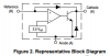
In this application, the TL431 is not used as a voltage regulator, but acts as a comparator with a built-in accurate and stable 2.5V reference voltage.
The TL531 functional block diagram below helps show how it can work as a comparator.

The TL431 Cathode transistor switches on when its Reference input voltage is above 2.5V and off when Ref is below 2.5V.
When on, this turns on transistor Q1, (connected to the Cathode), which energizes the relay.
When the voltage falls below the TL431's trigger point it turns off Q1 and thus denergizes the relay.
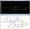
The LTspice simulation is shown below.
The Vb voltage where V(Ref) equals 2.5V is determined by the voltage divider consisting of resistors R2, R3, and the hysteresis feedback resistor R4.
For the values shown, that occurs at a nominal 12.40V (yellow trace) as the voltage is dropping, turning off the relay.
That value should leave at least 70% charge remaining in the battery which should be enough to start the engine.
The circuit turns the relay back on at a voltage of ≈13.56V or a little more than 1V above the turn-off voltage, as determined by the R4 hysteresis feedback resistance.
Thus the turn-on voltage is determined by R2, and R3, and the turn-off voltage is determined by R2, R3, and R4.
If you want the voltages to be adjustable, you can replace R2 with a 41.2kΩ resistor in series with a 5kΩ pot, which will change both voltages.
You can change the hysteresis value by changing R4, but note that will also change the turn-off voltage.
The relay can be an automotive type, 12V SPST relay.

Here is a circuit using a TL431 voltage reference IC to accurately turn off an accessory relay at the desired voltage.
In this application, the TL431 is not used as a voltage regulator, but acts as a comparator with a built-in accurate and stable 2.5V reference voltage.
The TL531 functional block diagram below helps show how it can work as a comparator.
The TL431 Cathode transistor switches on when its Reference input voltage is above 2.5V and off when Ref is below 2.5V.
When on, this turns on transistor Q1, (connected to the Cathode), which energizes the relay.
When the voltage falls below the TL431's trigger point it turns off Q1 and thus denergizes the relay.
The LTspice simulation is shown below.
The Vb voltage where V(Ref) equals 2.5V is determined by the voltage divider consisting of resistors R2, R3, and the hysteresis feedback resistor R4.
For the values shown, that occurs at a nominal 12.40V (yellow trace) as the voltage is dropping, turning off the relay.
That value should leave at least 70% charge remaining in the battery which should be enough to start the engine.
The circuit turns the relay back on at a voltage of ≈13.56V or a little more than 1V above the turn-off voltage, as determined by the R4 hysteresis feedback resistance.
Thus the turn-on voltage is determined by R2, and R3, and the turn-off voltage is determined by R2, R3, and R4.
If you want the voltages to be adjustable, you can replace R2 with a 41.2kΩ resistor in series with a 5kΩ pot, which will change both voltages.
You can change the hysteresis value by changing R4, but note that will also change the turn-off voltage.
The relay can be an automotive type, 12V SPST relay.