Occasionally it can be useful to generate only the maximum or minimum output of two or more analog input signals, or accurately clamp a signal between two levels.
The three simple op amp circuits here perform those functions.
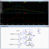
Below is the LTspice simulation for the max value circuit, shown for three inputs.
As can be seen, the output closely follows the input that has the maximum voltage.

---------------------------------------------------------
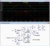
By reversing the diodes and connecting the output resistor to V+, the circuit becomes a minimum value circuit as shown below.
Here the simulation shows the output following the input that has the minimum voltage.
The circuit is also useful as a hard clamp circuit if a fixed clamp voltage is applied to one of the inputs.
Due to the single supply operation of the simulated circuit, the minimum output voltage for the min value circuit will be about 0.7V.

Both the above circuits can have an arbitrary number of inputs just by adding more op amps and diodes to the circuit.
-------------------------------------------
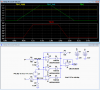
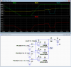
Below is the circuit configured to provide a hard, accurate bi-level clamp at the Ref_High and Ref_Low voltages (simulated at +5V and -5V respectively) for a single input.
The two Ref voltages can be anywhere in the dynamic range as long as Ref_High is more positive than Ref_Low.
This can be useful if a signal voltage has to be be accurately clamped within desired limits even if the signal source goes outside those limits.
The Ref voltages can be from any source and can be dynamically changed during circuit operation, if desired (programmable clamp).

The three simple op amp circuits here perform those functions.
Below is the LTspice simulation for the max value circuit, shown for three inputs.
As can be seen, the output closely follows the input that has the maximum voltage.
---------------------------------------------------------
By reversing the diodes and connecting the output resistor to V+, the circuit becomes a minimum value circuit as shown below.
Here the simulation shows the output following the input that has the minimum voltage.
The circuit is also useful as a hard clamp circuit if a fixed clamp voltage is applied to one of the inputs.
Due to the single supply operation of the simulated circuit, the minimum output voltage for the min value circuit will be about 0.7V.
Both the above circuits can have an arbitrary number of inputs just by adding more op amps and diodes to the circuit.
-------------------------------------------
Below is the circuit configured to provide a hard, accurate bi-level clamp at the Ref_High and Ref_Low voltages (simulated at +5V and -5V respectively) for a single input.
The two Ref voltages can be anywhere in the dynamic range as long as Ref_High is more positive than Ref_Low.
This can be useful if a signal voltage has to be be accurately clamped within desired limits even if the signal source goes outside those limits.
The Ref voltages can be from any source and can be dynamically changed during circuit operation, if desired (programmable clamp).
-
 upload_2017-5-1_19-35-35.png
 -
Max Value Ckt.asc
-
Min Value Ckt.asc
-
 upload_2017-5-6_12-45-9.png
 -
 upload_2017-5-6_12-49-16.png
 -
Clamp Accurate Ckt.asc
-
 upload_2017-5-6_19-31-48.png
