The 555 monostable timer circuit is commonly used when a one-shot pulse of up to a minute or so is desired as initiated by an input trigger.
In some designs, particularly battery operated circuits, it is desirable that the circuit use no power when not triggered and the circuit is quiescent.
Discussed here is a modification of a typical 555 one-shot circuit that uses a couple of transistors to remove the power when the one-shot output is over.
An added bonus is that these transistors also significantly boost the available output source current above the 555's nominal output.
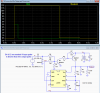
The circuit and LTspice simulation are shown below.
Transistors Q1 and Q2, which provide the output signal (and power to the 555), are initially off, so the only current drawn is their sub-microamp leakage currents.

A V2 positive trigger pulse turns on Q1 and Q2, which generates an output voltage, V(output), ≈equal to the supply voltage, V+.
(Note this is the opposite trigger polarity as compared to the 555 TRIG input).
This turns on the 555 and initiates the output pulse. The 555 OUT voltage then keeps Q1 and Q2 turned on for the duration of the pulse in bootstrap fashion.
When the OUT pulse terminates, Q1 and Q2 turn off, placing the circuit back into its zero power quiescent state
The one-shot period is determined by the R2C1 value and can be changed as needed.
D1 and C2 are used to prevent retriggering of the 555 if the input trigger pulse is longer than the output pulse.
If the trigger will always be shorter than the output pulse, than D1 and C2 are not needed.
The output can deliver a current up to 300mA or so at a 12V supply voltage.
The available current will be less at lower supply voltages unless the bias resistors of Q1 and Q2 are reduced accordingly.
Higher load currents can be provided by changing Q2 to a power P-MOSFET.
In some designs, particularly battery operated circuits, it is desirable that the circuit use no power when not triggered and the circuit is quiescent.
Discussed here is a modification of a typical 555 one-shot circuit that uses a couple of transistors to remove the power when the one-shot output is over.
An added bonus is that these transistors also significantly boost the available output source current above the 555's nominal output.
The circuit and LTspice simulation are shown below.
Transistors Q1 and Q2, which provide the output signal (and power to the 555), are initially off, so the only current drawn is their sub-microamp leakage currents.
A V2 positive trigger pulse turns on Q1 and Q2, which generates an output voltage, V(output), ≈equal to the supply voltage, V+.
(Note this is the opposite trigger polarity as compared to the 555 TRIG input).
This turns on the 555 and initiates the output pulse. The 555 OUT voltage then keeps Q1 and Q2 turned on for the duration of the pulse in bootstrap fashion.
When the OUT pulse terminates, Q1 and Q2 turn off, placing the circuit back into its zero power quiescent state
The one-shot period is determined by the R2C1 value and can be changed as needed.
D1 and C2 are used to prevent retriggering of the 555 if the input trigger pulse is longer than the output pulse.
If the trigger will always be shorter than the output pulse, than D1 and C2 are not needed.
The output can deliver a current up to 300mA or so at a 12V supply voltage.
The available current will be less at lower supply voltages unless the bias resistors of Q1 and Q2 are reduced accordingly.
Higher load currents can be provided by changing Q2 to a power P-MOSFET.