Select Mains Frequency.
50Hz 60Hz
|
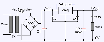
Regulated Power Supply, Full Wave Rectified 50/60Hz, C1 Smoothing Capacitor. V2 [25-Dec-13] The [Blue] plot is the full wave rectified voltage. The [Yellow] plot is the Regulator input voltage.[due to the action of the Smoothing cap C1]. The [Red] line is the minimum input voltage required by the regulator [Vdrop+Vreg]. If the Vcap [Yellow] plot falls below the [Red] line, the regulated output voltage will fail/drop. |
|
Select Mains Frequency. 50Hz 60Hz
TXrms=Rated Voltage. |
|
Placing the mouse pointer on the plots will show plot values. Enter into the text boxes the parameters as specified in the components Datasheet Fit a heatsink to the Regulator as required. There is an assumed loss of two diode forward voltage drops.[2*0.7v] from the transformers secondary voltage due to the bridge rectifier diodes. |