Continue to Site

Welcome to our site!

Electro Tech is an online community (with over 170,000 members) who enjoy talking about and building electronic circuits, projects and gadgets. To participate you need to register. Registration is free. Click here to register now.

  • Welcome to our site! Electro Tech is an online community (with over 170,000 members) who enjoy talking about and building electronic circuits, projects and gadgets. To participate you need to register. Registration is free. Click here to register now.

ZEZJ zero error zero jitter period algorithm

Status
Not open for further replies.

Mr RB

Well-Known Member
Hi, I've just updated my "zero error 1 second timer routines" page, there is a new section at the bottom that now supports zero-jitter period generation.

Like the other code on the page it will generate any period (or frequency) from any xtal using juts one simple constant to set theperiod. But this new system generates the period with zero jitter (which many people have requested). It is now useful for xtal-locked signal generation etc like to generate exactly 50Hz output or a 1 second clock signal etc.

The algortihm and code may not be immediately obvious so I will explain the basics;

ZEZJ algorithm;
(first, #define PERIOD in TMR0 ticks)
1. generate X interrupts of 100 ticks length
2. generate 1 interrupt of "remainder" length 100-199
3. done! make the event (toggle PIC pin etc)

It is "zero-error" as the interrupt always subtracts the 100 tick period (or remainder period) from TMR0, so that any immediate latency will be corrected on the next interrupt.

It is "zero jitter" because the remainder period syncs to the #defined PERIOD so the event (toggle PIC pin) always happens at exactly PERIOD.

The clever part is the "X*100 + remainder 100-199" because it means that the end of PERIOD can can never conflict with the TMR0 interrupt! This is because subtracting 100-199 will always result in a legal TMR0 count that will be corrected on the next int. So the result is that you can just #define PERIOD and it will automatically generate an exact jitter free period with no messy timing conflicts.

# Note! If you wanted to use the code below to generate other xtal-locked frequencies, you just need to change the PERIOD value (and maybe the xtal);
# toggle PERIOD = (xtal / 4 / freq / 2)
# 1 second; 4MHz xtal, PERIOD = 500000
# 50 Hz; 8MHz xtal; PERIOD = 20000
# 60 Hz; 6MHz xtal, PERIOD = 12500
# 60 Hz; 12MHz xtal, PERIOD = 25000
# 1 second; 8.867238MHz cheap TV xtal, PERIOD = (8867238 / 4 / 2)

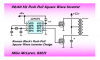
Here is the code to generate 50Hz with a PIC 12F675 4MHz xtal.
Code:
/******************************************************************************
  ZeroJitter.c   Generates zero-error and zero jitter interrupt period.
  Open-source  -  21 Nov 2009  -  www.RomanBlack.com/one_sec.htm

  PIC 12F675, 4MHz xtal.
  This is like my zero-error 1 second timing system, that uses a convenient
  constant to set ANY period (with 1 timer tick resolution).
  However this system has zero jitter!
  Can be used to generate 1 second period, or 50Hz freq output etc.
******************************************************************************/

// PERIOD sets the pin toggle freq; toggle PERIOD = (xtal / 4 / freq / 2) 
#define PERIOD 10000   // (xtal 4Mhz) TMR0 1MHz, 10000 = 100Hz toggle (50Hz output)

#define PER_COUNTS ((PERIOD / 100) - 1)  // don't edit this!
#define PER_REMAINDER (PERIOD - (PER_COUNTS * 100))  // don't edit this!

unsigned int pcount;    // used in interrupt to count PER_COUNTS 
//-----------------------------------------------------------------------------


//+++++++++++++++++++++++++++++++++++++++++++++++++++++++++++++++++++++++++++++
void interrupt()
{
  //-----------------------------------------------------
  // this is the TMR0 overflow interrupt.
  // Note! TMR0 has a 3 tick write latency, writes must be -3
  //-----------------------------------------------------
  // check if time to toggle the output pin
  if(!pcount)
  {
    asm {
      movlw 0x01      ; // mask for pin 0
      xorwf GPIO,f    ; // toggle PIC pin GPIO.0
    }
    pcount = (PER_COUNTS+1);    // how many delays to make total
    TMR0 -= (PER_REMAINDER-3);  // first delay will be ==remainder
  }
  // else make a normal delay
  else
  {
    TMR0 -= (100-3);       // make another 100 tick delay
  }
  pcount--;
  //-----------------------------------------------------
  // clear the TMR0 overflow flag and exit
  INTCON.T0IF = 0;
}
//+++++++++++++++++++++++++++++++++++++++++++++++++++++++++++++++++++++++++++++


//=============================================================================
//   MAIN
//=============================================================================
void main ()
{
  //-----------------------------------------------------
  // PIC 12F675  setup ports
  ANSEL = 0;            // ADC off
  CMCON = 0x07;         // comparators off
  GPIO =   0b00000000;  // clear GPIO
  TRISIO = 0b00000000;  // All outputs
  WPU =    0b00000000;  // pin pullups; 1 = pullup on (for button)

  //-----------------------------------------------------
  // timer setup etc
  OPTION_REG = 0b00001000;    // TMR0 on, 1:1 prescale
  pcount = 0;
  INTCON = 0b10100000;  // GIE on, T0IE on (turn interrupt on) 

  //-----------------------------------------------------
  // main run loop here
  while(1)
  {
    continue;   // loop and do nothing, just let the interrupt happen
  }
}
//-----------------------------------------------------------------------------

This can be used on even the smallest cheapest PICs, I deliberately chose TMR0 for this reason. ROM needed is about 54, RAM needed is 2.

Code was programmed and tested out perfectly, all values of PERIOD >=100.

There is more info here;
https://www.romanblack.com/one_sec.htm
 
Last edited:
Asm?

Hi Roman,

I love your stuff and have used your Zero-error algorithm before.
I was searching for it to use in my latest Project and found this post, which is even better suited to my application. However, being new to PIC's, I have acquired a reasonable level of competence in assembler, (I worked with 6089 Micro's 30 years ago) but have no experience in C, nor do I have a C compiler.
Whilst I can try to reverse engineer your C code, into Assembler, may I impose on you to present an assembler version of the code? even a disassembled C object file would help, but I suspect the maths calls will be relatively inefficient compared to the optimised 24 maths of the original assembler implementation.

Thanks for sharing
Cheers
Chris
 
Last edited:
Sure that's an easy request. I deliberately used C-- (my name for C that was written to work like asm) so it would compile very small and fast, and can be easily converted to asm.

And MikroC helps a lot because it makes these neat .ASM files so you can inspect the output asm and fine tune your C-- code;

Code:
;  ASM code generated by mikroVirtualMachine for PIC - V. 7.0
;  Date/Time: 21/11/09 5:10:56 PM
;  Info: http://www.mikroelektronika.co.yu


; ADDRESS	OPCODE	ASM
; ----------------------------------------------
$0000	$282A			GOTO	_main
$0004	$	_interrupt:
$0004	$00DF			MOVWF	STACK_15
$0005	$0E03			SWAPF	STATUS, 0
$0006	$0183			CLRF	STATUS
$0007	$00A3			MOVWF	?saveSTATUS
$0008	$0804			MOVF	FSR, 0
$0009	$00A2			MOVWF	?saveFSR
$000A	$080A			MOVF	PCLATH, 0
$000B	$00A4			MOVWF	?savePCLATH
$000C	$018A			CLRF	PCLATH
;ZeroJitter.c,23 :: 		void interrupt()
;ZeroJitter.c,30 :: 		if(!pcount)
$000D	$0820			MOVF	_pcount, 0
$000E	$0421			IORWF	_pcount+1, 0
$000F	$1D03			BTFSS	STATUS, Z
$0010	$281A			GOTO	L_interrupt_0
;ZeroJitter.c,33 :: 		movlw 0x01      ; mask for pin 0
$0011	$3001			MOVLW	0x01
;ZeroJitter.c,34 :: 		xorwf GPIO,f    ; toggle PIC pin GPIO.0
$0012	$0685			XORWF	GPIO, f
;ZeroJitter.c,36 :: 		pcount = (PER_COUNTS+1);    // how many delays to make total
$0013	$3064			MOVLW	100
$0014	$00A0			MOVWF	_pcount
$0015	$3000			MOVLW	0
$0016	$00A1			MOVWF	_pcount+1
;ZeroJitter.c,37 :: 		TMR0 -= (PER_REMAINDER-3);  // first delay will be ==remainder
$0017	$3061			MOVLW	97
$0018	$0281			SUBWF	TMR0, 1
;ZeroJitter.c,38 :: 		}
$0019	$281C			GOTO	L_interrupt_1
$001A	$	L_interrupt_0:
;ZeroJitter.c,42 :: 		TMR0 -= (100-3);       // make another 100 tick delay
$001A	$3061			MOVLW	97
$001B	$0281			SUBWF	TMR0, 1
;ZeroJitter.c,43 :: 		}
$001C	$	L_interrupt_1:
;ZeroJitter.c,44 :: 		pcount--;
$001C	$3001			MOVLW	1
$001D	$02A0			SUBWF	_pcount, 1
$001E	$1C03			BTFSS	STATUS, C
$001F	$03A1			DECF	_pcount+1, 1
;ZeroJitter.c,47 :: 		INTCON.T0IF = 0;
$0020	$110B			BCF	INTCON, 2
;ZeroJitter.c,48 :: 		}
$0021	$	L_Interrupt_end:
$0021	$0824			MOVF	?savePCLATH, 0
$0022	$008A			MOVWF	PCLATH
$0023	$0822			MOVF	?saveFSR, 0
$0024	$0084			MOVWF	FSR
$0025	$0E23			SWAPF	?saveSTATUS, 0
$0026	$0083			MOVWF	STATUS
$0027	$0EDF			SWAPF	STACK_15, 1
$0028	$0E5F			SWAPF	STACK_15, 0
$0029	$0009			RETFIE
$002A	$	_main:
;ZeroJitter.c,55 :: 		void main ()
;ZeroJitter.c,59 :: 		ANSEL = 0;            // ADC off
$002A	$1303			BCF	STATUS, RP1
$002B	$1683			BSF	STATUS, RP0
$002C	$019F			CLRF	ANSEL, 1
;ZeroJitter.c,60 :: 		CMCON = 0x07;         // comparators off
$002D	$3007			MOVLW	7
$002E	$1283			BCF	STATUS, RP0
$002F	$0099			MOVWF	CMCON
;ZeroJitter.c,61 :: 		GPIO =   0b00000000;  // clear GPIO
$0030	$0185			CLRF	GPIO, 1
;ZeroJitter.c,62 :: 		TRISIO = 0b00000000;  // All outputs
$0031	$1683			BSF	STATUS, RP0
$0032	$0185			CLRF	TRISIO, 1
;ZeroJitter.c,63 :: 		WPU =    0b00000000;  // pin pullups; 1 = pullup on (for button)
$0033	$0195			CLRF	WPU, 1
;ZeroJitter.c,67 :: 		OPTION_REG = 0b00001000;    // TMR0 on, 1:1 prescale
$0034	$3008			MOVLW	8
$0035	$0081			MOVWF	OPTION_REG
;ZeroJitter.c,68 :: 		pcount = 0;
$0036	$01A0			CLRF	_pcount
$0037	$01A1			CLRF	_pcount+1
;ZeroJitter.c,69 :: 		INTCON = 0b10100000;  // GIE on, T0IE on (turn interrupt on)
$0038	$30A0			MOVLW	160
$0039	$008B			MOVWF	INTCON
;ZeroJitter.c,73 :: 		while(1)
$003A	$	L_main_2:
$003A	$283A			GOTO	L_main_2
;ZeroJitter.c,77 :: 		}
$003B	$283B			GOTO	$

Note the MikroC interrupt context saving and restore is a little more than you really need for this project, but the compiler just does that automatically.
 
  • Like
Reactions: 3v0
Thanks Roman, Much appreciated.

And thanks for the compiler recommendation.
I Think I have just about mastered the midrange (or at least fully grasped, I'm a long way from being a master), and have ordered some PIC18 Chips to play with. My intention was to dive into Learning C when I got onto the more Powerful CPU's, so I will take a look at MikroC.
 
Zero error is a bit deceptive, the algorithm still as a granularity that can't be avoided.
 
A granularity? It will generate zero jitter exact 50:50 duty output, at a frequency adjustable to the finest possible resolution you can get with a PIC (1 TMR0 tick) with no errors. It doesn't get any better than that from a zero jitter 50:50 system.

If you need a finer-adjusted frequency that what is possible from 1 timer tick it is necessary to dither the output to give greater freq resolution, which is what my other "zero-error" timer routines do. They can make incredibly fine resolution freq output, but of course since that exceeds what is possible from the PIC timer it involves jitter.
 
Ok, with all the talk of inverters on the forum lately I whipped up a couple of projects. This one is a xtal-locked zero-jitter push-pull inverter that will output 50Hz with a 10Mhz xtal, or 60Hz with a 12MHz xtal (using the same code).

Code is fully tested and works very nicely, it uses the zero-jitter example above but generates 8 times the mains frequency, then the two push-pull outputs are sequenced like this;
Code:
GP0 - 01110000
GP1 - 00000111

This makes a pretty decent push-pull squarewave so it can be connected directly to a pair of FETs, so basically this is the entire code for a xtal-locked mains inverter for times when you need a very precise mains frequency generated;

Code:
/******************************************************************************
  ZJ_Inverter.c   xtal-locked push-pull Inverter driver
  Open-source  -  30 Nov 2009  -  www.RomanBlack.com/one_sec.htm

  PIC 12F675, xtal (see below).
  This was based on my ZEZJ system for generating a frequency.
  It will drive push-pull FETs to make a mains inverter;
    10MHz xtal; 50Hz output (same code is used for both)
    12MHz xtal; 60Hz output  
  GP0 - this is push-pull outputA (hi = FET on)
  GP1 - this is push-pull outputB (hi = FET on)
  
_BODEN_OFF _MCLRE_OFF _PWRTE_ON _WDT_OFF _HSOSC
******************************************************************************/

// edit PERIOD to give the freq; PERIOD = (xtal / 4 / (freq*8))
// Note! we need 8 period events per mains cycle, so use (freq * 8)
#define PERIOD 6250   // 10Mhz xtal = 50Hz, 12MHz xtal = 60Hz.

#define PER_COUNTS ((PERIOD / 100) - 1)  // don't edit this!
#define PER_REMAINDER (PERIOD - (PER_COUNTS * 100))  // don't edit this!

unsigned int pcount;    // used in interrupt to count PER_COUNTS 
unsigned char outputs;  // shadow register used to drive output pins
unsigned char outcount; // used to sequence the outputs
//-----------------------------------------------------------------------------


//+++++++++++++++++++++++++++++++++++++++++++++++++++++++++++++++++++++++++++++
void interrupt()
{
  //-----------------------------------------------------
  // this is the TMR0 overflow interrupt.
  // Note! TMR0 has a 3 tick write latency, writes must be -3
  //-----------------------------------------------------
  // check if period has occured
  if(!pcount)
  {
    // first send the outputs with no latency
    asm {
      movf outputs,w      ; // send this value out to PIC pins
      movwf GPIO          ;
    }
    pcount = (PER_COUNTS+1);    // how many delays to make total
    TMR0 -= (PER_REMAINDER-3);  // first delay will be ==remainder

    // now handle push-pull output sequencing;
    // 01110000   GP0
    // 00000111   GP1
    outcount++;
    if(outcount >= 8) outcount = 0;         // 8 steps in sequence
    if(outcount == 0) outputs = 0b00000000; // load outputs ready to be used
    if(outcount == 1) outputs = 0b00000001;
    if(outcount == 4) outputs = 0b00000000;
    if(outcount == 5) outputs = 0b00000010;
  }
  // else make a normal delay
  else
  {
    TMR0 -= (100-3);       // make another 100 tick delay
  }
  pcount--;
  //-----------------------------------------------------
  // clear the TMR0 overflow flag and exit
  INTCON.T0IF = 0;
}
//+++++++++++++++++++++++++++++++++++++++++++++++++++++++++++++++++++++++++++++


//=============================================================================
//   MAIN
//=============================================================================
void main ()
{
  //-----------------------------------------------------
  // PIC 12F675  setup ports
  ANSEL = 0;            // ADC off
  CMCON = 0x07;         // comparators off
  GPIO =   0b00000000;  // clear GPIO
  TRISIO = 0b00000000;  // All outputs

  //-----------------------------------------------------
  // timer setup etc
  OPTION_REG = 0b00001000;    // TMR0 on, 1:1 prescale
  pcount = 0;
  outputs = 0;
  outcount = 0;
  INTCON = 0b10100000;  // GIE on, T0IE on (turn interrupt on) 

  //-----------------------------------------------------
  // main run loop here
  while(1)
  {
    continue;   // loop and do nothing, just let the interrupt happen
  }
}
//-----------------------------------------------------------------------------
 
This next one came out very nice, I am quite pleased with it considering the very small simple code. It is a mains-locked 50Hz to 60Hz converter with push-pull inverter outputs basically its a complete inverter that sync-locks to the mains frequency.

This has been discussed a bit recently, for people who want to run old 60Hz clocks on 50Hz or vice versa.

The procedure is simplicity itself;
1. 4MHz xtal generates error corrected 600Hz pulses
2. Each incoming 50Hz mains cycle causes 12 pulses to be generated.
3. Every 10 pulses it generates a 60Hz push-pull cycle.
(it works perfectly for 60Hz to 50Hz conversion too, just edit one line of code)

**broken link removed**

This is the entire brain for a proper mains-locked freq-converting inverter so you can run old clocks from different frequency mains. Code is fully tested and looks VERY nice on the CRO; :D

Code:
/******************************************************************************
  ZE_MainsConverter.c   mains freq converter push-pull inverter driver
  Open-source  -  30 Nov 2009  -  www.RomanBlack.com/one_sec.htm

  PIC 12F675, 4MHx xtal 
  This was based on my zero-error reduced-jitter system that
  generates accurate 50Hz mains locked to 60Hz mains input,
  or vice versa. The output frequency will be exact, as it is
  locked to the input frequency. Generally this code would be
  used to make a small inverter to drive an antique 60Hz mains
  clock from 50Hz mains etc. The mains input can be as simple
  as a diode and a voltage divider pot from 12v AC to PIC pin GP2,
  so it gives half-cycle mains freq input of 0v-5v at the PIC pin.

  GP2 - mains freq input (see above)  
  GP0 - this is push-pull outputA (hi = FET on)
  GP1 - this is push-pull outputB (hi = FET on)
  
_BODEN_OFF _MCLRE_OFF _PWRTE_ON _WDT_OFF _HSOSC
******************************************************************************/

#define PERIOD 1667    // note! PERIOD is 1667 for either conversion!
#define PERHI (PERIOD / 256)          // don't edit this!
#define PERLO (PERIOD - (PERHI*256))  // don't edit this!

// now select one of these 2 options;
#define OUTPULSES 12   // 50Hz in, 60Hz out
//#define OUTPULSES 10   // 60Hz in, 50Hz out

unsigned char pulse;    // to generate output pulses
unsigned char outputs;  // shadow register used to drive output pins
unsigned char outcount; // used to sequence the outputs
//-----------------------------------------------------------------------------


//=============================================================================
//   MAKE OUTPUT       this generates the output frequency
//=============================================================================
void make_output(void)
{
  //-----------------------------------------------------
  // first send the outputs to PIC pins (no latency)
  GPIO = outputs;

  // then sequence the PIC pins
  #if OUTPULSES == 12    // if 60Hz output
  {
    // 0011100000   GP0  (sequence of 10 pulses = one 60Hz cycle)
    // 0000000111   GP1
    outcount++;
    if(outcount >= 10) outcount = 0;        // 10 steps in sequence
    if(outcount == 0) outputs = 0b00000000; // load outputs ready to be used
    if(outcount == 2) outputs = 0b00000001;
    if(outcount == 5) outputs = 0b00000000;
    if(outcount == 7) outputs = 0b00000010;
  }
  #else      // else is 50Hz output
  {
    // 001111000000   GP0  (sequence of 12 pulses = one 50Hz cycle)
    // 000000001111   GP1
    outcount++;
    if(outcount >= 12) outcount = 0;        // 12 steps in sequence
    if(outcount == 0) outputs = 0b00000000; // load outputs ready to be used
    if(outcount == 2) outputs = 0b00000001;
    if(outcount == 6) outputs = 0b00000000;
    if(outcount == 8) outputs = 0b00000010;
  }
  #endif
}
//-----------------------------------------------------------------------------


//=============================================================================
//   MAIN
//=============================================================================
void main ()
{
  //-----------------------------------------------------
  // PIC 12F675  setup ports
  ANSEL = 0;            // ADC off
  CMCON = 0x07;         // comparators off
  GPIO =   0b00000000;  // clear GPIO
  TRISIO = 0b00000100;  // GP2 is mains input, rest outputs

  T1CON = 0b00000001;   // TMR1 on, 1:1 prescale (1MHz)

  pulse = 0;            // and setup vars
  outputs = 0;
  outcount = 0;

  //-----------------------------------------------------
  // main run loop here
  while(1)
  {
    while(!GPIO.F2);      // wait for mains / edge to occur
    pulse = OUTPULSES;    // set number of outputpulses to make
    TMR1L = 7;            // rig TMR1 like a pulse just happened
    TMR1H = 0;
    goto do_pulse;        // make first pulse straight away!

    // now repeat this section until all pulses are made
    while(pulse)
    {
      while(!PIR1.TMR1IF);   // wait for TMR1 to roll (1 period)
      do_pulse:
      TMR1L -= PERLO;        // fix TMR1, retain error for next period
      TMR1H -= (PERHI + 1);
      PIR1.TMR1IF = 0;

      make_output();      // make the output pulse
      pulse--;
    }
  }
}
//-----------------------------------------------------------------------------

These push-pull inverters are also on my zero-error timing routines page;
Zero-error 1 second timing algorithm
 
Last edited:
Roman (Mr RB),

Concerning 50/60 Hz Inverters, would there be any advantage using a 50 Hz or 60 Hz sine wave generator?

Regards, Mike

Code:
/********************************************************************
 *                                                                  *
 *  Project: Sine 50-60                                             *
 *   Source: Sine_50-60.c                                           *
 *   Author: Mike McLaren, K8LH                                     *
 *     Date: 03-Dec-09                                              *
 *  Revised: 03-Dec-09                                              *
 *                                                                  *
 *  12F683 50/60 Hz PWM Sine Wave Generator experiment uses fifty   *
 *  pwm intervals to construct a sine wave spanning 50,000 cycles   *
 *                                                                  *
 *  60-Hz output = 16.667-msec period using a 12-MHz crystal        *
 *  50-Hz output = 20.000-msec period using a 10-MHz crystal        *
 *                                                                  *
 *                                                                  *
 *      IDE: MPLAB 8.14 (tabs = 4)                                  *
 *     Lang: SourceBoost BoostC v6.95, Lite/Free version            *
 *                                                                  *
 ********************************************************************/

#include <system.h>

#pragma DATA _CONFIG, _FCMEN_OFF&_IESO_OFF&_MCLRE_OFF&_WDT_OFF&_HS_OSC


const rom char sine[] = { 125,140,156,171,185,198,210,221,230,238,
                          243,247,249,249,247,243,238,230,221,210,
                          198,185,171,156,140,124,109,093, 78, 64,
                           51, 39, 28, 19, 11,  6,  2,  0,  0,  2,
                            6, 11, 19, 28, 39, 51, 64, 78, 93,109 };

unsigned char n = 0;        // sine table index, 0..49

void interrupt()            //
{ pir1.TMR2IF = 0;          // clear TMR2 interrupt flag
  ccpr1l = sine[n++];       // setup next duty cycle
  if(n = 50) n = 0;         // reset index at end-of-period
}

void main()                 //
{                           //
  cmcon0 = 7;               // comparator off, digital I/O
  ansel = 0;                // a2d module off, digital I/O
  trisio = 0;               // set all pins to outputs
  gpio = 0;                 // set all output latches to '0'
  pir1 = 0;                 // clear peripheral interrupt flags
  pie1.TMR2IE = 1;          // set Timer 2 interrupt enable bit
  tmr2 = 0;                 // clear Timer 2 register
  ccp1con = 0b00001100;     // '00------' unimplemented bits
                            // '--00----' DC1B1:DC1B0 duty cycle bits
                            // '----1100' active hi PWM mode
  t2con = 0b00000101;       // '0-------' unimplemented bit
                            // '-0000---' TOUTPS<3:0>, postscale 1
                            // '-----1--' TMR2ON, turn Timer 2 on
                            // '------01' T2CKPS<1:0>, prescale 4
  pr2 = 250-1;              // 250 x prescale 4 = 1000 instruct cycles
  intcon = 0b11000000;      // '1-------' GIE, enable global ints
                            // '-1------' PEIE, enable peripheral ints
                            // '--0-----' T0IE, TMR0 ints disabled
                            // '---0----' INTE, off
                            // '----0---' GPIE, IOC disabled
                            // '-----000' T0IF/INTF/GPIF flags

  while(1)                  // main program loop
  {                         //
  }                         //
}
 
Last edited:
Very nice simple elegant code. CCP modules make life easy huh. ;)

Sinewave inverter is definitely superior, but for driving 5 watt clocks with synchronous motors then a modified squarewave will work just as well.

You code does lack push-pull outputs too, they are pretty important driving a little transformer.

All you would have to do to add that feature is manually detect the PWM event (not in an int) and manually set the 2 push-pull output pins. Manually testing the flag only costs a 0-2 inst (0-0.8uS with 10MHz xtal) latency per PWM pulse which self corrects every PWM pulse anyway. Considering the low freq that would work fine, and you would get 2 complimentary PWM outputs without needing an enhanced PWM module AND still have a high efficiency sinewave.

And after that step it would not be much more effort to remove the CCP module completely and manually use TMR1 and TMR0, which woul dmake the code workable on just about any of the bottom end 8pin PICs.

Also you might want to double check these lines;
Code:
 *  50-Hz output = 16.667-msec period using a 12-MHz crystal        *
 *  60-Hz output = 20.000-msec period using a 10-MHz crystal        *
:)

(edit)Here's a thought, you could keep your code as is, and use the PIC comparator set to mode 011 to perform a hardware inversion of your PWM output. ie attach PWM output to comparator Cin- then Cout goes out to PIC pin and gives the inverted PWM output so you get 2 push-pull outputs from the same tiny elegant code.
 
Last edited:
Thanks you for the nice comments Roman. I corrected that typo' in the program listing.

Could that single-ended sine wave output drive a push-pull transistor pair or would that circuitry be too complex?

I agree that you don't need a CCP module to implement a jitter free cycle accurate pair of sine wave outputs. Or for a pair of push-pull square wave outputs for that matter. You don't even need a timer module. You could do it all with a simple isochronous loop on a six pin 10F200 if necessary.

<added>

The comparator module as an inverter for the complimentary sine wave signal is a good idea.

Regards, Mike
 
Last edited:
...
Could that single-ended sine wave output drive a push-pull transistor pair or would that circuitry be too complex?

It only really needs an extra transistor to invert the signal for one FET. But the really nice solution I think is to just use a PIC and drive 2 FETs direct from the PIC pins so the PIC acts as a complete brain.

I agree that you don't need a CCP module to implement a jitter free cycle accurate pair of sine wave outputs. Or for a pair of push-pull square wave outputs for that matter. You don't even need a timer module. You could do it all with a simple isochronous loop on a six pin 10F200 if necessary.
...

I'd like to see your isochronous loop solution. Even with a 4MHz xtal a 50Hz cycle takes 20000 instructions.

What would work with limited ROM would be to use 50 small loops, each hardcoded to generate your 50 sinewave PWM values. Then keep your 250 inst TMR2 interrupt, and just inc n and forcibly jump into each timing loop. No int context saving is needed. You actually only need 25 timing loops and sequence 0-24 then 24-0 in the interrupt.

I did something like that years ago which generated 300 kHz dual phase PWM on an old PIC 16F84A (!) for microstepping a 2 phase stepper motor.
 
It only really needs an extra transistor to invert the signal for one FET. But the really nice solution I think is to just use a PIC and drive 2 FETs direct from the PIC pins so the PIC acts as a complete brain.
You're right. A single chip solution is better.
I'd like to see your isochronous loop solution. Even with a 4MHz xtal a 50Hz cycle takes 20000 instructions.
It wouldn't take much more then one of my "cycle accurate" fixed delay subsystems (macro and 9 word subroutine) and a simple isochronous loop like this for push-pull square wave output;
Code:
;******************************************************************
;  Zero Jitter 50 or 60 Hz push-pull square wave output (12F675)  *
;******************************************************************
;  60-Hz output = 16.667-msec period (12-MHz osc - 50000 cycles)  *
;  50-Hz output = 20.000-msec period (10-MHz osc - 50000 cycles)  *
;******************************************************************
        radix   dec
pCycles equ     50000/8         ; cycles_in_period/8 = 6250
;
;  GP0  _-------------____________________
;  GP1  __________________------------____
;       |   16.667-msecs / 20.000-msecs   |
;
NewPeriod
        movlw   b'00000001'     ;                                 |B0
        movwf   GPIO            ;                                 |B0
        DelayCy(3*pCycles-1)    ; GP0 "on" for 3/8ths period      |B0
        clrf    GPIO            ;                                 |B0
        DelayCy(1*pCycles-2)    ; GP1:GP0 "off" 1/8th period      |B0
        movlw   b'00000010'     ;                                 |B0
        movwf   GPIO            ;                                 |B0
        DelayCy(3*pCycles-1)    ; GP1 "on" for 3/8ths period      |B0
        clrf    GPIO            ;                                 |B0
        DelayCy(1*pCycles-4)    ; GP1:GP0 "off" 1/8th period      |B0
        goto    NewPeriod       ;                                 |B0
;
rb-sine-wave-2-png.36069

Now correct me if I'm wrong but couldn't we just drive the N-FET inputs with filtered sine wave patterns like those below to produce sine wave output instead of square wave output?

rb-sine-wave-1-png.36070


If that's all that's required then I think it could be done quite easily without a CCP module or timer modules using just a simple isochronous loop. I'll take a try at this code in the next few days.

Regards, Mike
 

Attachments

  • RB Sine Wave 2.PNG
    RB Sine Wave 2.PNG
    18.5 KB · Views: 5,659
  • RB Sine Wave 1.PNG
    RB Sine Wave 1.PNG
    8.2 KB · Views: 3,867
You made a beautiful schematic image (as always ;)) but it's probably best described as "Ultra-simple push-pull modified square wave inverter" rather than using my name as it is really a standard push pull inverter topology, just using the minimum parts that will actually do the job.

That's tiny code for getting the job done. It would be nice to include the macro too if someone wants to build it. This page looks like it's becoming a resource for building tiny inverters which is pretty cool. :)

As for using the RC filters and driving the FETs with analog sines, that's a bad idea because it runs the FETs in the linear region where they will dissipate a lot of power so inverter efficiency is low and the FETs now need to be big and have big heatsinks.

Your original PWM sine is far better for efficiency, provided of course it has the dual push-pull PIC outputs.
 
I hope you don't mind Mike but I merged my 50Hz to 60Hz converter code into your nice PWM sine generator code.

This generates 24 "virtual pulses" (using TMR1) for every 50Hz incoming mains cycle.

Then it generates the output 60Hz sine over 20 of those virtual pulses, hence making a 24:20 period conversion so the 60Hz sine output is freq locked to the 50Hz mains input and remains as perfect as the national grid.

Also I changed the PWM period to 100 instructions (instead of your 1000 instructions) this bumps the PWM freq from 2.5kHz up to a nice 25kHz, giving less noise and easier filtering by the output transformer. It will need a new PWM table with 20 values in the 0-99 count range.

The interrupt does nothing now, as the PWM period is automatic (every 100 instructions) and asynchronous to both the incoming and output mains frequencies. This is useful because it allows freq conversion in either direction with no hassles because the PWM does not need to be synced to either mains freq.


Code:
/********************************************************************
 *                                                                  *
 *  Project: Sine 50Hz to 60Hz converter                            *
 *   Source: HybridSine_50-60.c                                     *
 *   Author: Mike McLaren, K8LH (main code and sine routines)       *
 *   Author2:RomanBlack (24:20 routine for 50Hz to 60Hz convert)    *
 *     Date: 07-Dec-09                                              *
 *  Revised: 07-Dec-09                                              *
 *                                                                  *
 *  12F683 60 Hz PWM sinewave output  to drive small inverter.      *
 *  PIC is freq locked to 50Hz mains frequency input, and converts  *
 *  50Hz input to a 60Hz sine output. (not yet hardware tested)     *
 *  NOTE! TO drive push-pull outputs this requires a hardware       *
 *  inverter to make the 2nd output, a transistor will do.          *
 *                                                                  *
 *      IDE: MPLAB 8.14 (tabs = 4)                                  *
 *     Lang: SourceBoost BoostC v6.95, Lite/Free version            *
 *                                                                  *
 *  GP2 - CCP1 - PWM sinewave output                                *
 *  GP3 - 50Hz freq in (must be filtered 0v-5v)                     *
 *                                                                  *
 ********************************************************************/

#include <system.h>

#pragma DATA _CONFIG, _FCMEN_OFF&_IESO_OFF&_MCLRE_OFF&_WDT_OFF&_HS_OSC

#define PERIOD 2083    // for 50Hz input and 10MHz xtal (50Hz / 24)
#define PERHI (PERIOD / 256)          // don't edit this!
#define PERLO (PERIOD - (PERHI*256))  // don't edit this!

// 60Hz output; sine table needs 20 entries, 0-99 range as PWM is 100 cycles
const rom char sine[] = { 49,64,78,89,96,99,96,89,78,64,
                          49,34,20,9,2,0,2,9,20,34};

unsigned char n = 0;        // sine table index, 0..19
unsigned char pulse;        // for pulse sequencing

void interrupt()            //
{
  pir1.TMR2IF = 0;          // clear TMR2 interrupt flag
  // nothing else needed in int now!
}

void main()                 //
{                           //
  cmcon0 = 0x07;            // comparator not used!
  ansel = 0;                // a2d module off, digital I/O
  trisio = 0b00001010;      // GP3 is freq in, GP1 is Cin
  gpio = 0;                 // set all output latches to '0'
  pir1 = 0;                 // clear peripheral interrupt flags
  pie1.TMR2IE = 1;          // set Timer 2 interrupt enable bit
  tmr2 = 0;                 // clear Timer 2 register
  ccp1con = 0b00001100;     // '00------' unimplemented bits
                            // '--00----' DC1B1:DC1B0 duty cycle bits
                            // '----1100' active hi PWM mode
  t1con = 0b00000001;       // TMR1 on, at 1:1 prescale
  t2con = 0b00000101;       // '0-------' unimplemented bit
                            // '-0000---' TOUTPS<3:0>, postscale 1
                            // '-----1--' TMR2ON, turn Timer 2 on
                            // '------00' T2CKPS<1:0>, prescale 1:1
  pr2 = 100-1;              // 100 x prescale 1:1 = 100 instruct cycles
  intcon = 0b11000000;      // '1-------' GIE, enable global ints
                            // '-1------' PEIE, enable peripheral ints
                            // '--0-----' T0IE, TMR0 ints disabled
                            // '---0----' INTE, off
                            // '----0---' GPIE, IOC disabled
                            // '-----000' T0IF/INTF/GPIF flags

  while(1)                  // main program loop
  {                   
    // loop here and do the freq conversion; 24:20 (50Hz in, 60Hz out)
    while(!GPIO.F3);        // wait for 50Hz mains / edge to occur
    pulse = 24;             // set number of pulses per 50Hz cycle
    TMR1L = 0;              // rig TMR1 like a pulse just happened
    TMR1H = 0;
    goto do_pulse;          // make first pulse straight away!

    // now repeat this section until all pulses are made
    while(pulse)
    {
      while(!PIR1.TMR1IF);  // wait for TMR1 to roll (1 period)
      do_pulse:
      TMR1L -= PERLO;       // fix TMR1, retain error for next period
      TMR1H -= (PERHI + 1);
      PIR1.TMR1IF = 0;

      // make the output pulse
      ccpr1l = sine[n];     // setup next sine duty cycle
      n++;                  // 20 sine steps = 60Hz cycle
      if(n >= 20) n = 0;

      pulse--;              // one more input pulse processed
    }
  }                        
}

If you wanted to adapt this code to do 60Hz in to 50Hz out, it would need a 24 entry sine table, and do 24:20 inversion;
Code:
    pulse = 24;           change to;  pulse = 20;
    if(n >= 20) n = 0;  change to;  if(n >= 24) n = 0;
and still use the 10MHz xtal.

(edit) This only makes a single PWM sine output, so if push-pull outputs are needed it requires a hardware inverter to generate outputB by generating and inverted outputA. A transistor and couple of resistors would be enough to do the hardware inversion.
 
Last edited:
Not sure I follow your 50 to 60 Hz convertors but anyway, is this the sine table you're looking for?

Happy Holidays. Mike

Code:
Number of steps: 20
   Output range: 99
 Table or Array: t

        retlw   049             ; 000  +0
        retlw   064             ; 001  +0.30901699
        retlw   078             ; 002  +0.58778525
        retlw   089             ; 003  +0.80901699
        retlw   096             ; 004  +0.95105652
        retlw   099             ; 005  +1
        retlw   096             ; 006  +0.95105652
        retlw   089             ; 007  +0.80901699
        retlw   078             ; 008  +0.58778525
        retlw   064             ; 009  +0.30901699
        retlw   049             ; 010  -0.41020686e-9
        retlw   034             ; 011  -0.30901699
        retlw   020             ; 012  -0.58778525
        retlw   009             ; 013  -0.80901699
        retlw   002             ; 014  -0.95105652
        retlw   000             ; 015  -1
        retlw   002             ; 016  -0.95105652
        retlw   009             ; 017  -0.80901699
        retlw   020             ; 018  -0.58778525
        retlw   034             ; 019  -0.30901699
 
Last edited:
Hehe I knew you would have a neat PERL app or EXCEL something to generate the sine values and save me reaching for my X2 and doing it the hard way.

Thanks, the sine values have been added into code above.

(edit) Here are a couple of pictures showing how the mains freq-locked 50Hz to 60Hz conversion works and why it only needs such simple code; :)
 

Attachments

  • onesec03.gif
    onesec03.gif
    30.4 KB · Views: 817
  • onesec04.gif
    onesec04.gif
    32.7 KB · Views: 828
Last edited:
Status
Not open for further replies.

Latest threads

New Articles From Microcontroller Tips

Back
Top