Continue to Site

Welcome to our site!

Electro Tech is an online community (with over 170,000 members) who enjoy talking about and building electronic circuits, projects and gadgets. To participate you need to register. Registration is free. Click here to register now.

  • Welcome to our site! Electro Tech is an online community (with over 170,000 members) who enjoy talking about and building electronic circuits, projects and gadgets. To participate you need to register. Registration is free. Click here to register now.

zener shunt stabiliser

Status
Not open for further replies.

Kane2oo2

New Member
Hey all
picked up a new book today on power supplies (in an attempt to try and increase my 'limited' knowledge of electronics)

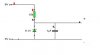
the circuit in question is attached below (although values not set - but just downloaded croc clips quickly and couldnt work out how to turn values off)

am i understanding this right? if the unstabilised input voltage from the left of the circuit increases (above zener voltage) it starts to conduct, which means the decoupling capacitor will "take over" until the voltage is back to normal and then if the voltage drops below the zener voltage it will also conduct meaning the capacitor will be used?

just wanted to clear this up :)

Thanks
Kane
 

Attachments

  • shunt.JPG
    shunt.JPG
    5.8 KB · Views: 565
No Kane, you do not appear to be understanding the circuit.

When the supply voltage is below the Zener voltage, the Zener is off and the capacitor is charged to whatever the voltage is. If a load is applied, the voltage will decrease in proportion.

When the supply voltage is above the Zener voltage, the Zener is on and current flows through it. The capacitor is charged to the Zener voltage.

If a load is applied, current flows through the load and the Zener current decreases. But the voltage does not decrease very much. So the voltage is regulated at the Zener voltage (about 5.1 Volt)

Provided that the current taken by the load is less than the current through the Zener before the load was applied, the voltage will be regulated. Once the load current exceeds this value, the voltage will decrease in proportion.

Your circuit shows that the supply voltage is 9 Volt and the resistor is 10k. Thus with no load, the Zener current will be about 9 - 5.1)/10k = 3.9/10 = 3.9 mA.

So the voltage will be regulated at about 5.1 Volt provided the load is less than 3 mA. At a load of 3 mA there will be 0.9 mA through the Zener thus it is still on. But if the load increases, the voltage will decrease gradually until the load current reaches 3.9 Volt and then it will decrease in proportion thereafter.

The capacitor is provided in order to provide a low AC source impedance. It does not provide regulation.

Len
 
More or less, I write it in my own words:

- A zener diode is a component that, when connected like in your circuite, will conduct as much current as needed (till its limits) to keep the voltage drop on it as it's nominal value (in your case 5.1v)

- A capacitor charged at a voltage X will try to keep that voltage constant (till it has charge enough to do so)

So if the voltage goes over 5.1v the zener will start to allow current across it and do all it can to keep the voltage to 5.1, if the voltage goes lower the zener can do nothing about it and the capacitor will try to help as long as it can.

That way you get your output stabilized, provided that the input voltage doesn't go too much high (zener fries) or goes too low (capacitor cannot help anymore).
 
diode said:
That way you get your output stabilized, provided that the input voltage doesn't go too much high (zener fries) or goes too low (capacitor cannot help anymore).

This statement is misleading.

The capacitor can only maintain the voltage for a very short time. In the circuit shown, if the load was 3 mA, the load resistance would be about 5.1/3 = 1.7k. Thus the time constant would be 1 uF x 1.7k = 1.7 millisecond. This means that if the 9 Volt supply was switched off, the voltage would fall to zero within 1.7 x 5 millisecond, ie. about 8.5 millisecond.

Len
 
ljcox ...as i said these values werent calculated ..they were the default values in the circuit design program

so who is right? lol
 
yes ljcox is right, in a way it was misleading, I only tryed to give a simple words explanation as it seems it's what he was asking for.

Anyhow it's true, capacitor can help only to reduce ripple on the output, surely cannot keep power up forever.
 
there is just one thing i dont understand
When the supply voltage is above the Zener voltage, the Zener is on and current flows through it. The capacitor is charged to the Zener voltage.

if the zener is "on" and the current is flowing straight through it ....how can the capacitor be charged?

Kane
 
When the Zener is on, there is about 5.1 Volt across it. So the capacitor charges to this voltage.

Len
 
so if this is used as a stabilised supply and the voltage increases, the zener turns on and starts to charge the capacitor... so how does this create a constant output if it is only charging the cap?
 
When the input (9 volts) starts from zero, all the current goes to charge the capacitor, until the voltage reaches 5.1 volts where the zener turns on. Thereafter, no current goes to the capacitor, it all goes thru the zener. The purpose of the capacitor is to supply pulse current to the load. The load could draw more than 3 mA for a short time, pulling the current from the capacitor.
 
ljcox said:
<snip>Your circuit shows that the supply voltage is 9 Volt and the resistor is 10k. Thus with no load, the Zener current will be about 9 - 5.1)/10k = 3.9/10 = 3.9 mA.<snip>Len
That should be 3.9/10k=390ua.
 
Kane2oo2 said:
so if this is used as a stabilised supply and the voltage increases, the zener turns on and starts to charge the capacitor... so how does this create a constant output if it is only charging the cap?

Ignore the capacitor, it doesn't really affect the working of the circuit, in fact remove the capacitor completely!.

A zener diode 'breaks down' at a certain specified voltage (the BE junction of a transistor does exactly the same, and can be used as zener).

When you apply power to the circuit, 9V will appear on the top end of the resistor - the voltage on the top of the zener will try to rise to 9V as well, but as soon as it reaches 5.1V the zener will break down. If the diode turns on really hard the voltage across it will become less than 5.1V, so it turns off again, and the voltage will rise again. This all happens extremely quickly, the result being that you get a steady 5.1V (roughly) on the top of the zener diode.

Incidently, a neon bulb can be used in a similar way (and has been in the past) - but because a neon bulb has a large difference between it's on and off levels, it can be used as a relaxation oscillator.
 
hey nigel
thats exactly what i was trying to explain ... and then the capacitor is simply used to "soften" this noise of the quick switching?

but then ljcox said something about the capacitor being charged by the zener ...which totally threw me off!

Thanks alot
Kane
 
The 5.1 volt zener has a positive resistance, it won't turn on and off. One advantage of 5.1 volts is that the temperature coefficient is close to zero. Lower voltages have have a negative coefficient, higher voltages are positive.
 
Russlk said:
The 5.1 volt zener has a positive resistance, it won't turn on and off. One advantage of 5.1 volts is that the temperature coefficient is close to zero. Lower voltages have have a negative coefficient, higher voltages are positive.

Very true, it's why you find 5.1V zeners commonly used as the reference in power supplies.
 
Nigel Goodwin said:
Russlk said:
The 5.1 volt zener has a positive resistance, it won't turn on and off. One advantage of 5.1 volts is that the temperature coefficient is close to zero. Lower voltages have have a negative coefficient, higher voltages are positive.

Very true, it's why you find 5.1V zeners commonly used as the reference in power supplies.
Nigel, Russ was referring to this statement you made:
If the diode turns on really hard the voltage across it will become less than 5.1V, so it turns off again, and the voltage will rise again.
It also had me baffled. It implies negative resistance.
 
Ron H said:
Nigel, Russ was referring to this statement you made:
If the diode turns on really hard the voltage across it will become less than 5.1V, so it turns off again, and the voltage will rise again.

I don't think so?.

It also had me baffled. It implies negative resistance.

Sorry, I don't see what you are getting at?.
 
Nigel said:
If the diode turns on really hard the voltage across it will become less than 5.1V, so it turns off again, and the voltage will rise again.
Maybe I'm misunderstanding this statement. Can you paraphrase it?
 
Ron H said:
Nigel said:
If the diode turns on really hard the voltage across it will become less than 5.1V, so it turns off again, and the voltage will rise again.
Maybe I'm misunderstanding this statement. Can you paraphrase it?

I don't see how I could make it much simpler, I think your problem may be trying to think of it as a resistance - which it's not.

Try thinking of it as a Vbe junction of a transistor, this requires 0.7V to turn on, and it will hold the voltage at no more than 0.7V once turned on.

A zener works in the same way, except it's more than 0.7V.

And, just like the Vbe junction, you need a current limiting resistor to stop it destroying itslef.
 
Nigel said:
If the diode turns on really hard the voltage across it will become less than 5.1V, so it turns off again, and the voltage will rise again.
Current goes up (diode turns on hard) - voltage goes down. I'm paraphrasing, but that's what I understand this statement to mean. This is negative resistance. Zeners don't have negative resistance. In a zener, dv/di is always positive, on any portion of the V-I curve.
 
Status
Not open for further replies.

Latest threads

Back
Top