Electro Tech is an online community (with over 170,000 members) who enjoy talking about and building electronic circuits, projects and gadgets. To participate you need to register. Registration is free. Click here to register now.
Welcome to our site! Electro Tech is an online community (with over 170,000 members) who enjoy talking about and building electronic circuits, projects and gadgets. To participate you need to register. Registration is free. Click here to register now.
Hi, i have a 3.3v Zener diode in series with a current limiting resistor (any value within range) but its output is about 3.8volts? can anyone shed some light on WHY its not 3.3volts?
Zeners are not perfect voltage regulators. The voltage may go higher than the rated value for some current levels. The lower voltage ones are the worst.
You might find some data looking up the part number that may help.
hi,
Checked the d/s for that 1 Watt zener, it states 3.3V ok.
Tried a few test currents with a 1N4728 using LTspice, all around 3.3V.
What supply voltage and resistors have you tried.?
My first reaction was that the characterisic curve of a low voltage zener was very soft, as intimated by Mr Al.
Many years ago I had a bad experience with low voltage zeners due to this very problem.
However, looking at the datasheets and from your experience it looks a though these zeners are much better than those from the "middle ages"!
It sounds as though you have a cheap imitation or a reject which has been labeled in a 3rd world back street knock off sweat shop!
Does Jaycar sell poor quality "failed" parts like RadioShack did?
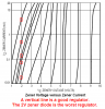
I agree that a low voltage zener diode has poor voltage regulation. Its voltage also changes as its temperature changes.
Here are some graphs that show impedance and the voltage increasing as the current increases:
Does Jaycar sell poor quality "failed" parts like RadioShack did?
I agree that a low voltage zener diode has poor voltage regulation. Its voltage also changes as its temperature changes.
Here are some graphs that show impedance and the voltage increasing as the current increases:
The reason for me wanting to set up a 3.3v voltage divider/regulator, is because i have a car instrument cluster running about 7 12v globes all in parallel... i want to change the power supply for the lights from 12v to 3.3v and replace the globes with LED's with a forward voltage of 3.3v... is this a practical way of doing this?
LEDs set their own voltage which is a range of voltages. You need to limit their current, not their voltage.
If the "3.3V" LEDs are 3.0V to 3.6V and the car electical voltage is 13.8V, you can connect one to three LEDs in series and in series with a current-limiting resistor.
Maybe the car switches in a lower voltage to dim the "globes" at night then three LEDs in series will not work.
Use simple arithmatic to calculate the value of the current-limiting resistor.
I can't connect them in series (if i could i would) the instrument cluster is set up in parallel and is fed from one 12v supply, i could scratch out some of the tracks and set them all up in parallel, each with there own resistor or even some series sets! but i was looking for a more practical way first...
This site uses cookies to help personalise content, tailor your experience and to keep you logged in if you register.
By continuing to use this site, you are consenting to our use of cookies.

")